
Section 17.3 · Chapter 17: Increase Efficiency
Link Overview
Link Overview shows the relations between devices/servers and
panels of the entire project. The Link Overview is a block and line diagram. The
block indicates a target panel or the device/server. The line indicates the
link. The line with an arrow header indicates the link relationship.
There are two types of blocks in the link overview window: Target Panel Block
and Device/Server Block.
The Target Panel Block includes application Name and supported link ports, such
as C stands for COM port (C1 = COM1), E stands for Ethernet port. The
Device/Server Block includes the device type.
To open the Link Overview, check the Link Overview menu item in the View menu.
The following is an example of the Link Overview.
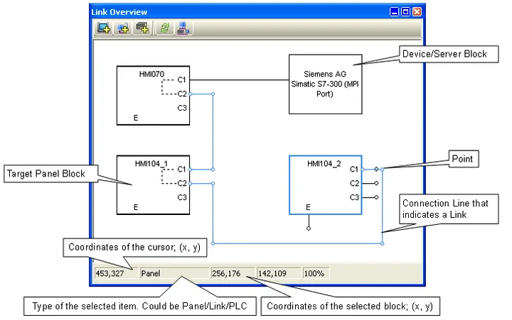
You can position the mouse over a target panel block, a device/server block, or a link to select the related item. With the selected item, you may do the following:
■ Open the properties dialog to set up item properties
Double-click the target panel block to open the General Setup dialog box to set
up the panel application.
Double-click the link to open the Link Properties dialog box to set up the link.
Double-click the device/server block to open the Link Properties property sheet
to select the device for the link.
■ Move the selected block
Left-click anywhere inside the selected block and hold down the button. When the
cursor changes to  , drag the mouse to move the selection to another area of the
link overview window. It will "float" over the rest of the window, allowing you
to position it wherever you want it to be. Release the mouse button to "let go"
of the selection.
■ Shape the connection line
Position the mouse pointer over one of the points on the selected connection
line, drag the point until the connection line is the shape and size you want.
■ Create a link
1. Position the mouse pointer over the point of the communication port. For
example:
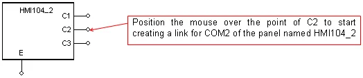
2. Drag the mouse to move the point to the communication port of another panel or device/server. For example:

3. Release the mouse button to bring up the Link Properties dialog box to set up the new link.
4. Press the OK button to accept the settings or press the Cancel button to cancel the operations. The following is an example of the new links between two panels.
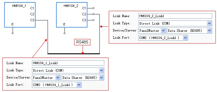
The following table describes each icon in the Link Overview window.
|
Icon |
Tool Tip | Description |
|---|---|---|
 |
Add Panel Application | Add a new panel application, set up the panel type and application name in the pop-up property sheet. |
 |
Add Link | Add a new link for the selected panel and set up the link properties in the pop-up property sheet. Only available when the target panel is the current selection. |
 |
Add Device/Server | Add a new Device/Server. |
 |
Refresh | Reload the current relations between panels and the device/server of the project. |
 |
Show Relationship | Display lines with an arrow head to show the relationship between panels and the device/server. |
You can right-click the target panel block in the Link Overview to get the pop-up menu with the following menu items:
|
Menu Item |
Description |
|---|---|
| Add Link | Create a new communication link. |
| Delete Panel Application | Delete the panel application. |
| Panel Application Properties | Open the General Setup dialog box. |
You can right-click the link in the Link Overview to get the pop-up menu with the following menu items:
|
Menu Item |
Description |
|---|---|
| Insert Point | Add a point at the specified position. |
| Delete Point | Delete a selected point. |
| Delete Link | Delete the associated communication link. |
| Link Properties | Open the Link Properties dialog box of the associated communication link. |
You can right-click the blank place in the Link Overview to get the pop-up menu with the following menu items:
|
Menu Item |
Description |
|---|---|
| Add Device/Server | Create a new Device/Server |
| Add Panel Application | Create a new panel application. |
| Refresh | Reload the current relations between panels and device/server of the project. |
You can right-click the Device/Server block in the Link Overview to get the pop-up menu with the following menu items:
|
Menu Item |
Description |
|---|---|
| Remove Device/Server | Delete the selected Device/Server. |
| Device/Server Properties | Open the Link Properties dialog box |
Need PM Designer itself?
V4 for current PK, PT, ITV and PM panels, V2 for older models. Free, sent by email.
Source.Section 17.3 of the PM Designer Software User Manual, Edition 2.0, © Cermate Technologies Inc. (www.cermate.com, service@cermate.com). Reproduced online, with the manual's own figures, by TSL Automation Solutions, authorised Cermate distributor, for users of Cermate HMI panels. PM Designer and PanelMaster are trademarks of Cermate Technologies Inc.
Text and figures are the manufacturer's and may describe features your panel or software version does not have. For a plain-language introduction read the PM Designer guide; for help with a specific panel contact TSL Automation.