
Section 6.2.4 · Chapter 6: Lamps
Multistate Lamp - General Settings
This section describes how to define the general settings for a multi-state lamp. The following is an example of the General page of the Multi-state Lamp property sheet.
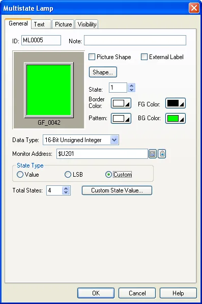
The following table describes each property in the General page.
|
Property |
Description | |
|---|---|---|
| ID | The object’s identifier. It is generated when the object is created. The identifier is unique within the screen where the object is located. The format of the IDs for the multi-state lamps is MLnnnn. | |
| Note | You can type a note for the object. | |
| Shape settings |
For details about the following properties, see
Section 4.3.4 Setting up the Shape of an Object , Picture Shape,
 ,
Border Color, Pattern, FG Color, BG Color |
|
| External Label | Check this option if you want the multi-state lamp to have an external label. Set up the external label in the External Label page. | |
| State | Select a state as the current state of the multi-state lamp so you can view and set the object appearance for that state. | |
| Data Type | The data type of the monitored variable. The supported data types include: 16-bit Unsigned Integer, 16-bit Signed Integer, 16-bit BCD, 32-bit Unsigned Integer, 32-bit Signed Integer, and 32-bit BCD. | |
| Monitor Address | Monitor Address |
Specifies the variable to be monitored. |
 |
Click this icon to bring up the Address Input Keypad and specify an address for the Monitor Address field. | |
 |
Click this icon to bring up the Select Tag dialog box and select a tag for the Monitor Address field. | |
| State Type | The state type for the state of the monitored variable. The supported state types include Value, LSB and Custom. For details, see Section 4.4.1.1 State Types. | |
| Total States | Specifies the number of states that the multi-state lamp can display. | |
 |
Click the button to bring up the Custom State Value dialog box to assign a positive integer for each state in the dialog box. Please see details in Section 4.4.1.2 Setting the Custom States of an Object. | |
Need PM Designer itself?
V4 for current PK, PT, ITV and PM panels, V2 for older models. Free, sent by email.
Source.Section 6.2.4 of the PM Designer Software User Manual, Edition 2.0, © Cermate Technologies Inc. (www.cermate.com, service@cermate.com). Reproduced online, with the manual's own figures, by TSL Automation Solutions, authorised Cermate distributor, for users of Cermate HMI panels. PM Designer and PanelMaster are trademarks of Cermate Technologies Inc.
Text and figures are the manufacturer's and may describe features your panel or software version does not have. For a plain-language introduction read the PM Designer guide; for help with a specific panel contact TSL Automation.