RS-232 vs RS-422 vs RS-485 on Industrial PCs: Wiring, Distance, Isolation
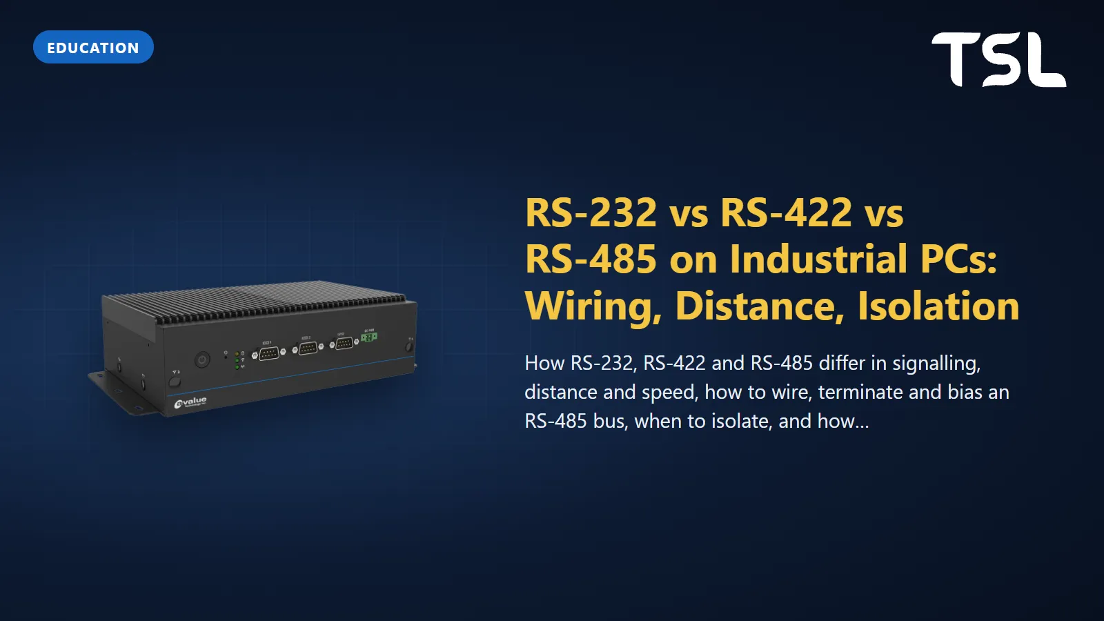
Table of Contents
RS-232 is a single-ended, point-to-point link for short cables: the standard specifies 20 kbit/s and a cable load that works out to about 15 to 20 m. RS-422 and RS-485 are differential (balanced) links that run up to about 1,200 m; RS-422 lets one transmitter talk to up to ten receivers, while RS-485 lets 32 unit loads share one bus, on one twisted pair (half duplex) or two (full duplex). On industrial PCs, one COM connector is often all three, selected in the BIOS.
Below: signalling, distance and speed, RS-485 wiring, termination, biasing, isolation and what to check on a box PC or HMI. Figures are from Texas Instruments application reports.
RS-232 vs RS-422 vs RS-485 at a glance
| RS-232 (TIA-232) | RS-422 (TIA/EIA-422) | RS-485 (TIA-485) | |
|---|---|---|---|
| Signalling | Single-ended, referenced to signal ground | Differential pair | Differential pair |
| Topology | Point to point | One driver, up to 10 receivers | Multipoint bus, up to 32 unit loads |
| Direction | Separate transmit and receive lines | One direction per pair | Half duplex on one pair, full duplex on two |
| Distance | 2,500 pF cable load, about 15 to 20 m | Up to about 1,200 m | 4,000 ft (about 1,200 m) at 100 kbps |
| Speed | 20 kbit/s in the standard; faster in practice on short cables | 10 Mbps common over short distances | 10 Mbps at 40 ft in the standard; faster transceivers exist |
| Receiver threshold | Plus or minus 3 V | 200 mV differential | 200 mV differential |
| Common-mode range | Not applicable (shared ground) | Receivers: -7 V to +7 V | -7 V to +12 V |
| Termination | None | Once, at the far end near the last receiver | At both ends of the bus |
Sources: TI Interface Circuits for TIA/EIA-232-F (SLLA037A), Comparing Bus Solutions (SLLA067C), RS-422 and RS-485 Standards Overview (SLLA070D) and The RS-485 Design Guide (SLLA272D).
RS-232: simple, short and ground-referenced
An RS-232 driver swings between about plus and minus 5 to 15 V, and the receiver reads anything above +3 V or below -3 V, leaving a 2 V noise margin. TI's design notes explain that the original 15 m limit of RS-232-C was replaced by a maximum capacitive load of 2,500 pF, which equates to about 15 to 20 m of cable, and that the standard specifies a maximum data rate of 20 kbit/s; with the 30 V/µs slew-rate limit the practical ceiling is around 120 kbit/s, and at higher rates lines are usually limited to around 3 m (TI SLLA037A). TI's bus comparison lists RS-232 as under 250 kbps and under 20 m, the figures modern transceivers achieve (TI SLLA067C).
Wiring is three wires for a basic link: transmit to receive, receive to transmit, ground to ground. On the 9-pin D-sub of a PC COM port, pin 2 is receive, pin 3 transmit and pin 5 signal ground; connecting two PCs needs the TX and RX lines crossed (a null-modem cable). RS-232 is the right choice for a barcode reader, a weighing scale or a modem in the same cabinet. Its weakness is the shared ground: once the two ends are on different supplies or in different buildings, ground noise appears directly on the signal.
RS-422 and RS-485: distance against speed
Differential signalling gives RS-422 and RS-485 their reach. An RS-485 driver delivers at least 1.5 V across the pair and a receiver must detect as little as 200 mV, and because noise couples equally into both wires of a twisted pair, the receiver rejects it as common-mode noise (TI SLLA272D).
Distance and data rate trade against each other. TI gives two rules of thumb:
- For RS-485, cable length in metres multiplied by data rate in bit/s should stay below 10,000,000 (10^7). TI calls this "far more conservative than today's cable performance". At very low rates, cable resistance becomes the limit: for 22 AWG, 120 Ω twisted pair, this happens at about 1,200 m (TI SLLA272D).
- For RS-422, the product of signalling rate and cable length should not exceed 100,000,000 (10^8); TI's example is a 500 m cable limited to 200 kbps (TI SLLA070D).
The 1,200 m and 10 Mbps headline figures are the two ends of that curve, never reached together. Applying the conservative RS-485 rule: 9,600 bit/s allows about 1,040 m, 115,200 bit/s about 87 m, and 1 Mbit/s about 10 m. If you need both high speed and long cable, plan an Ethernet backbone with serial at the edges. Our Modbus guide covers the protocol that most often rides on RS-485, and the fieldbus guide places RS-485 among the other industrial networks.
RS-485 wiring: 2-wire vs 4-wire
TI describes two RS-485 bus structures (TI SLLA272D):
- 2-wire (half duplex): one twisted pair carries data in both directions, so transmitting and receiving happen at different times. Every node has a driver-enable control so that only one driver is active at any moment; two drivers at once is bus contention, which the software must prevent.
- 4-wire (full duplex): two pairs, one for each direction, so a node can transmit and receive at the same time. A master talks on one pair and listens on the other; the slaves share the return pair and still take turns.
A 4-wire RS-485 link looks like RS-422, and RS-485 parts are generally interchangeable with RS-422 ones, but not the reverse: RS-422 drivers have a narrower common-mode range and are not designed to share a line with other drivers (TI SLLA070D).
Cable and topology
- Use twisted pair with 120 Ω characteristic impedance, typically 22 to 24 AWG (TI SLLA272D).
- Wire nodes as a daisy chain, not a star. Keep stubs from the trunk to each node short: TI's table allows about 7 ft at 1 Mbps with a 100 ns rise-time driver and about 38 ft at 200 kbps with a 500 ns driver.
- Vendors label the pair inconsistently (A/B, D+/D-, 485+/485-). If a new link does not respond, swapping the pair at one end is the first test.
Termination and biasing
Termination stops signal reflections. RS-485 recommends 120 Ω cable, so the trunk is terminated with a 120 Ω resistor at each end and nowhere else (TI SLLA272D). RS-422 has only one driver, so its single termination goes at the far end, next to the last receiver (TI SLLA070D). For RS-422, TI notes termination is required unless the data rate is below 200 kbps or the signal rise time at the load is longer than four times the one-way cable delay.
Biasing (failsafe) sets a known bus state when no driver is active. Without it, an idle bus can produce random bits. TI explains that modern transceivers include internal failsafe for open, short and idle bus, but with a worst-case noise margin of only 10 mV; in noisy plants an external pull-up and pull-down pair is added, and TI's example uses 523 Ω bias resistors with the two 120 Ω terminations (TI SLLA272D).
Biasing costs bus capacity. The standard requires drivers to handle 32 unit loads, failsafe biasing can take up to 20 of them, and so with 1/8 unit-load transceivers TI calculates a maximum of 96 devices rather than 256. In practice: bias the bus once, usually at the master, and leave the bias jumpers on the other nodes off.
Isolation: when the grounds disagree
On a long RS-485 run, the nodes draw power from different parts of the electrical installation, and the difference between their grounds adds to the signal as common-mode voltage. TI warns that a link inside the -7 V to +12 V common-mode range today can fail later when maintenance work raises that difference, and that tying remote grounds together with a wire creates ground-loop currents. The way to tolerate ground differences of up to several kilovolts is galvanic isolation of the transceiver's signal and supply, with one non-isolated node providing the reference for the bus (TI SLLA272D).
Choose isolated COM ports when the serial line leaves the cabinet: panels or buildings on separate supplies, cables near VFD motor leads, and outdoor equipment. Within one panel on one supply, a standard port with proper termination is usually enough.
BIOS-selectable COM modes on industrial boards
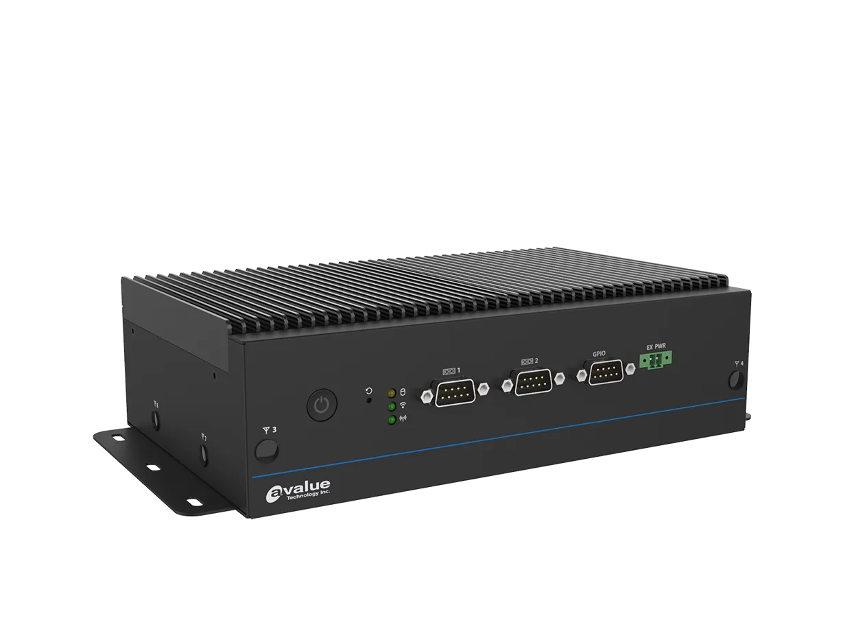
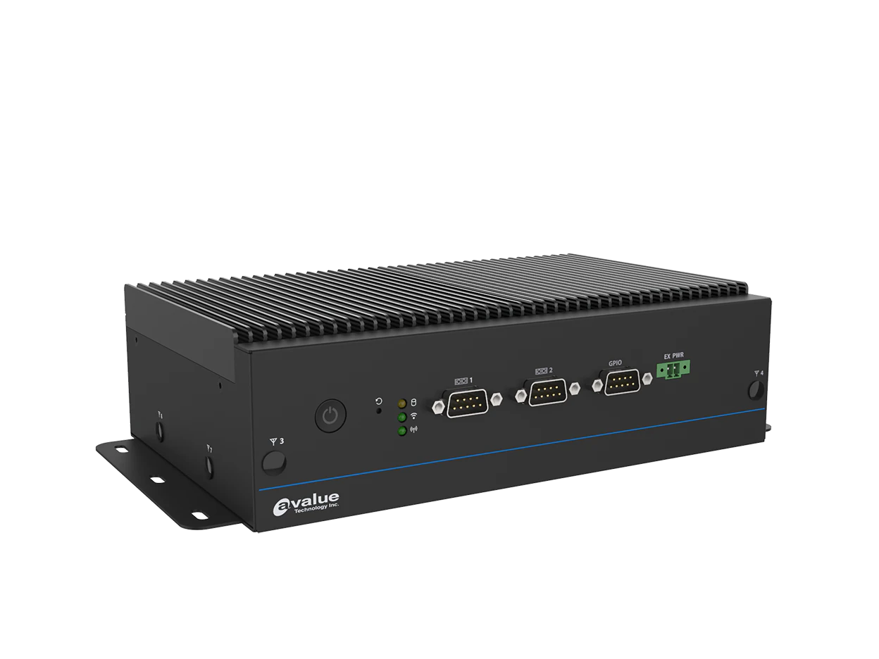
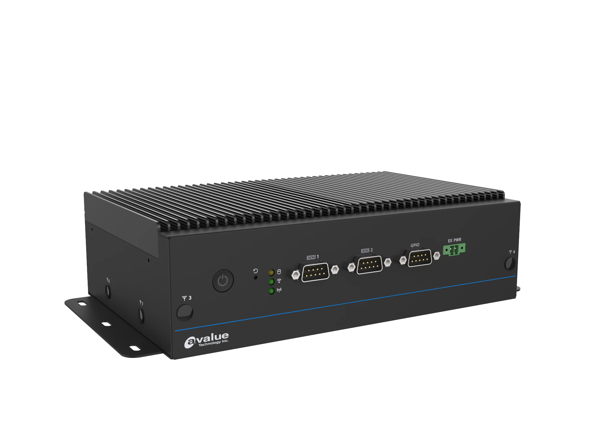
Industrial boards rarely have separate connectors per standard. One UART feeds a multi-protocol transceiver and the BIOS chooses the mode; Avalue's records describe this as "RS232/422/485 (select via BIOS)". Four points to check:
- Which ports are multi-mode. On the EMS-TGL-6COM all six ports are listed as BIOS-selectable; on the isolated EMS models the two front ports are BIOS-selectable and the four rear ports carry the isolation. Other products mix port types: the EMX-ASLP Thin Mini-ITX board has two RS-232/422/485 and four RS-232-only ports, and the EPS-RPS box PC four RS-232/422/485 and two RS-232. Count the ports you need in each mode, not the total, and check how the mode is set where the record does not say.
- Set the mode before wiring. The pin assignment on the connector changes with the mode, so follow the manual's pinout table for the selected mode.
- Direction control. In 2-wire RS-485 the driver must switch on only while transmitting. Avalue lists "auto flow control via HW" on the BIOS-selectable ports of the EMS models; confirm with your driver and software whether direction is switched by hardware or must be toggled by the application.
- Isolation is hardware. No BIOS setting can add it.
For choosing the board itself, see how to choose an embedded industrial motherboard.
Box PCs and HMIs with multiple COM ports
| Model | Type | Serial ports on the record | Notes |
|---|---|---|---|
| EMS-TGL-6COM | Fanless modular box PC, 11th Gen Intel Core | 6 x RS-232/422/485, all BIOS-selectable, HW auto flow control | 9 to 36 V DC terminal block; -40 to 70°C on WT SKU with airflow |
| EMS-EHL-4COM-isolation | Fanless modular box PC, Intel Elkhart Lake | 4 x RS-232/422/485 with 2.5KV isolation, plus 2 x BIOS-selectable RS-232/422/485 | 9 to 36 V DC with TVS surge protection; -40 to 70°C on x6425E SKU with airflow |
| EPS-RPS | Compact box PC, 13th Gen Intel Core | 4 x RS-232/422/485 + 2 x RS-232 | 5-pin terminal block power; -10 to 55°C fanless (35 W) |
| EMX-ASLP | Thin Mini-ITX board, Intel N97 or Atom x7433RE | 4 x RS-232 + 2 x RS-232/422/485 | 12 to 24 V DC; -20 to 70°C extended temperature option |
| IPK2070-31ST | Cermate 7" HMI | COM1 RS-232, COM2 RS-422/485, COM3 RS-485 (DB9); optional COM4 RS-485 and COM5 RS-485 or RS-232 on terminals | -10 to 60°C; IP65 front |
| ITV410-22 | Cermate 10.1" HMI | Standard: COM1 RS-232, COM2 RS-485 on a 5-pin terminal; optional types with RS-422 or dual RS-485 | Dual 10/100 LAN; -10 to 60°C; IP66 front |
Figures are from the product records on our site. Also in the range: the EMS-TGL-4COM isolation (Tiger Lake version), the EMS-TGL-Marine (four 2.5KV isolated ports, 9 to 36 V DC input with 1.5KV isolation) and the EPC-EHL-8COM (8 x RS-232 only). On ARC panel PCs, an optional ACC-ARC-COM-1R kit adds two isolated RS-232 ports.
Cermate HMI records list communication with up to six device types, set up in PM Designer, so one panel can read a PLC on RS-232 and drives or meters on RS-485. See the PM Designer guide.
How TSL can help
TSL Automation Solutions, based in Mumbai, has been an authorised Avalue and Cermate distributor since 2015 and ships worldwide. For serial-heavy projects we supply Avalue box PCs with BIOS-selectable and isolated COM ports (EMS-TGL-6COM, EMS-EHL-4COM-isolation, EMS-TGL-4COM isolation, EMS-TGL-Marine), the EPS-RPS with four RS-232/422/485 ports, embedded boards such as the EMX-ASLP, and Cermate HMIs with RS-232, RS-422 and RS-485 ports such as the IPK2070-31ST and ITV410-22. Try the product finder, or check two models' COM ports in the compare tool. Tell us how many ports you need in each mode, the cable lengths and whether the lines leave the cabinet.
Send us the model numbers and quantities and we will reply with availability and lead time within one business day.
Frequently Asked Questions
TSL Automation Solutions
Head of Marketing, TSL Automation Solutions
Sanjana covers industrial automation trends, product launches, and technology insights for TSL Automation Solutions, a Mumbai-based distributor of HMI, Panel PC, and embedded computing systems serving manufacturers across India and globally.
Need help choosing the right product?
Our team in Mumbai can recommend the right HMI, Panel PC, or embedded system for your application.
Contact TSL Automation