How to Connect a Cermate HMI to a PLC over Modbus TCP in PM Designer

Table of Contents
To connect a Cermate HMI to a PLC over Modbus TCP in PM Designer, give the panel its own IP address in Panel Setup, add a link with Link Type set to Direct Link (Ethernet), choose the Modbus TCP driver with "Device/Slave" in its name under Modicon Corp. (the PLC is the slave and the panel polls it), enter the PLC's IP address on the Parameter page, and address registers in Modbus notation such as 40001. Prove the link with on-line simulation from the PC, then compile and download.
The steps below follow our PM Designer guide, Chapter 3 (PLC communication) and the related chapters, so the menu names match what you will see. Where Modbus itself sets the rules (port 502, unit identifier, register numbering) we quote the Modbus Organization specifications.
Before you start
Collect five things from the PLC side. Most connection problems are a missing item from this list, not a software fault:
- The PLC's IP address and subnet mask, and a free address on the same subnet for the HMI.
- The TCP port. The Modbus TCP implementation guide reserves listening port 502 for Modbus and says all Modbus/TCP messages are sent to it, while recommending that devices let the user change the port for special cases (Modbus Messaging on TCP/IP Implementation Guide V1.0b).
- The register map: which values sit in coils, discrete inputs, input registers and holding registers, and their numbers.
- The data type of each value: 16-bit or 32-bit, signed or unsigned, BCD or floating point.
- An HMI with an Ethernet port. Not every Cermate model has one. The IPK2070-31ST has Ethernet, but the IPK2070-30ST lists it as N/A, so check the model suffix.
New to the protocol? Our article What is Modbus? explains the register types, and industrial Ethernet protocols compared shows where Modbus TCP fits against the alternatives.
Step 1: Set the HMI's own IP address
The panel's IP address is not set in the link. Per the guide, it belongs to the panel and is entered in its Panel Setup screen (General page: IP address, subnet mask and gateway), or written at runtime with the LINK_PAR macro. To reach Panel Setup from a running application, touch the top-left, top-right and top-left corners in turn; a red square blinks at each corner when the touch registers, provided "Allow To Run Panel Setup" is True (Chapter 11: download and simulate).
Pick an address outside the router's DHCP range and make sure no other device uses it. A duplicate address answers some pings and not others, which looks exactly like an intermittent cable fault.
Step 2: Add the link and choose the Modbus TCP driver
In the Project Manager, right-click Links and choose Add Link, or use Panel > Link > Add. On the General page of Link Properties set:
- Link name: something that will make sense in an alarm message, such as the PLC's name.
- Link Type: Direct Link (Ethernet).
- Device/Server: open Modicon Corp. and pick the TCP driver with "Device/Slave" in its name.
The driver name tells you which end the panel is, and getting it wrong is the classic mistake: as the guide's troubleshooting chapter notes, picking the wrong family gives silence, not an error.
| Choice in PM Designer | What the panel does | Use it when |
|---|---|---|
| Driver with "Device/Slave" in the name (RTU, ASCII or TCP) | The panel is the master and polls the device | The normal case: HMI reading and writing a PLC, drive or controller |
| "Quantum" variant (driver C2C081) | Panel is master, with extended addressing | You need addresses above 9999 or hexadecimal addressing |
| Driver with "Master" in the name | The panel is the slave and answers a master | A PLC or SCADA writes into the panel |
| Gateway Service link | The panel acts as a Modbus TCP or RTU server for a PC | SCADA must read the panel's memory, or PLCs on its other links, through the panel |
Links are numbered when they are created and the numbers shift down if an earlier link is deleted, so add links in a sensible order and leave them in place. Depending on the model, a panel application can have 4 or 16 links.
Step 3: Fill in the Ethernet parameters
For an Ethernet link the Parameter page asks for:
- IP address of the PLC (not the panel).
- Port: tick Use Default Port unless the PLC was configured to listen on another port.
- Node address, where the protocol needs one.
- Timeout Time, Retry Count and Command Delay, which decide how the driver behaves when the PLC is slow or absent.
On the node address, the Modbus specification is clear about what the unit identifier in a Modbus TCP message is for. It routes the request to a serial slave behind a gateway, where it carries that slave's address (1 to 247). A device connected directly to the network is addressed by its IP address, so the unit identifier is not significant there; the specification recommends 0xFF and notes that 0 is also accepted (Modbus Implementation Guide). In practice: if the IP address belongs to a TCP-to-serial gateway, use the serial slave address; if it is the PLC itself, follow the PLC manual.
If one Ethernet link must reach several Modbus devices, define them as sub-links on the Sub-link page, each with its own IP address. Addresses on a sub-link are written node:address.
Step 4: Address the registers and create tags
With the driver chosen, PM Designer uses the Modbus convention for addresses: 1 to 9999 and 10001 to 19999 are bits, 30001 to 39999 and 40001 to 49999 are words. Without a prefix an address refers to link 1; 2\40001 is the same register on link 2. The Address Input Keypad, opened from the small icon next to any address field, lists only the register types the chosen driver supports, which is the quickest way to learn its syntax.
Watch for the off-by-one. The Modbus Application Protocol specification numbers data elements from 1 to n in the data model but addresses them from 0 in the message: "a MODBUS data numbered X is addressed in the MODBUS PDU X-1" (Modbus Application Protocol Specification V1.1b3). If a PLC manual lists a holding register as "address 0", it is usually 40001 in this notation; if every value you read appears to come from the neighbouring register, this is why.
Then name the addresses with tags (Panel > Tags for local tags). A tag holds a name, address, data type and scan rate, so an object bound to a tag keeps working when the PLC address behind it changes, and the tag list becomes the interface document between the HMI and PLC programmers. Tags import and export as tab-delimited CSV, so a PLC symbol table can become an HMI tag list in minutes (Chapter 4: tags and internal memory).
Set the data type to match the PLC programmer's declaration. Modbus registers are 16-bit, so a 32-bit integer or float occupies two consecutive words; a 32-bit float read as a 16-bit integer gives garbage. If a 32-bit value still looks wrong, test with a known value and ask the PLC programmer which of the two words holds the high half. In macros, write 40001K when you mean the number 40001 rather than the register.
Step 5: Prove the link from the PC with on-line simulation
Before the panel is involved, save and compile, then run Tools > Run On-line Simulation. The PC uses its own network card with the project's link settings to talk to the real PLC, which proves the driver, IP address and register map on the bench. The PC needs an Ethernet connection on the same subnet as the PLC. Tools > Run Off-line Simulation is for screens and logic only: it uses virtual registers, so a communication error can never occur there.
Step 6: Compile and download
- Panel > Compile. Clear every error in the Build List window. "Address out of range" means the driver does not support that register type or number.
- Panel > Download. Under Link Settings choose Ethernet and type the panel's IP address (or USB with the driver installed).
- Tick Runtime Data and System Programs and Configuration Data, so the project can be uploaded from the panel later.
- Choose Safe Mode for large applications or any connection that has dropped mid-transfer.
Our guide's first project chapter walks through a complete small application if this is your first PM Designer project.
When the panel shows a communication error
Work from the cable up: physical layer first, then parameters, then addresses. The guide's troubleshooting chapter lists the checks in order:
- Ping the PLC and the panel from a PC on the same subnet. No reply is a network problem, not a PM Designer problem.
- Repeat on-line simulation with the same settings. If the PC cannot talk to the PLC either, look at wiring, the PLC's port configuration or the driver choice.
- Check what the panel is actually using. Panel Setup > Link n shows the IP address and settings in use. If someone edited them on the panel, "Communications Settings" on the General page decides whether the downloaded values or the panel's own values win.
- Check the driver role. "Device/Slave" makes the panel the master; "Master" makes it the slave.
- Look for one bad address. A single object reading a register the PLC does not have can hold the whole link in error.
A macro can read the link state with LINK_STS and act on it, for example by lighting a "PLC offline" lamp. The values that point to a Modbus TCP fault are:
| LINK_STS value | Meaning | Usual cause on Modbus TCP |
|---|---|---|
| 5, 7 | No response, timeout | Wiring, PLC power, or a wrong node address |
| 11, 12 | Invalid address, invalid range | An object addresses a register the PLC does not have |
| 20, 21 | Failed to open connection, connection not ready | IP address, port or firewall |
| 16 | Link disabled | The link or sub-link was switched off, for example with EN_LINK |
The full code list and a sample macro are in Chapter 3.
Which Cermate HMIs can do this
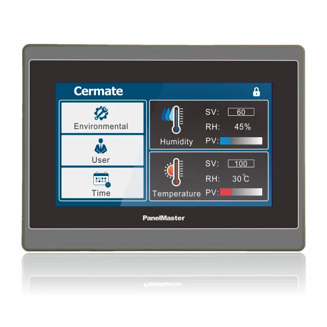
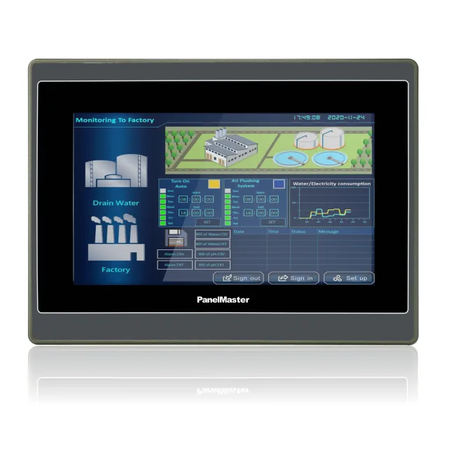
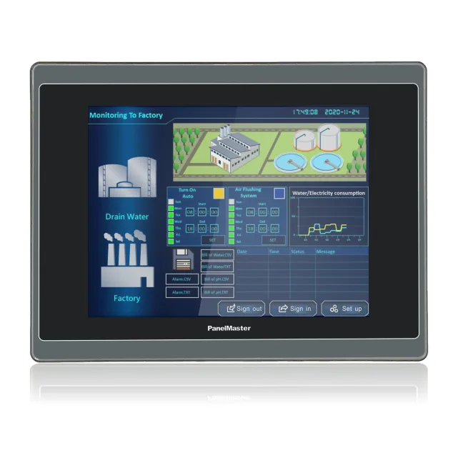
Any Cermate HMI with an Ethernet port that is programmed in PM Designer. From our records, examples include the IPK2070-31ST (7-inch, IP65), the IPT2070-51ST and IPT2100-51ST (7 and 10.1-inch, NEMA Type 4X / IP66), the IPM210 (10.1-inch, 10/100 Mbps Ethernet, PM Designer v4.0) and the ITV410-22 (10.1-inch with two 10/100 LAN ports). All of these also have serial ports, so one panel can talk to a Modbus TCP PLC and a Modbus RTU drive at the same time on separate links. See our HMI buying guide for choosing size and rating.
How TSL can help
TSL Automation Solutions, based in Mumbai, has been an authorised Cermate distributor since 2015 and ships worldwide. We supply Cermate HMIs with Ethernet in 4.3 to 15-inch sizes, programmed with PM Designer. Our PM Designer guide covers links, tags, alarms, recipes, macros and downloading chapter by chapter.
Send us the model numbers and quantities and we will reply with availability and lead time within one business day.
Frequently Asked Questions
TSL Automation Solutions
Head of Marketing, TSL Automation Solutions
Sanjana covers industrial automation trends, product launches, and technology insights for TSL Automation Solutions, a Mumbai-based distributor of HMI, Panel PC, and embedded computing systems serving manufacturers across India and globally.
Need help choosing the right product?
Our team in Mumbai can recommend the right HMI, Panel PC, or embedded system for your application.
Contact TSL Automation