Wide-Voltage Industrial PCs: 9-36 V DC Input, Ignition Control and UPS
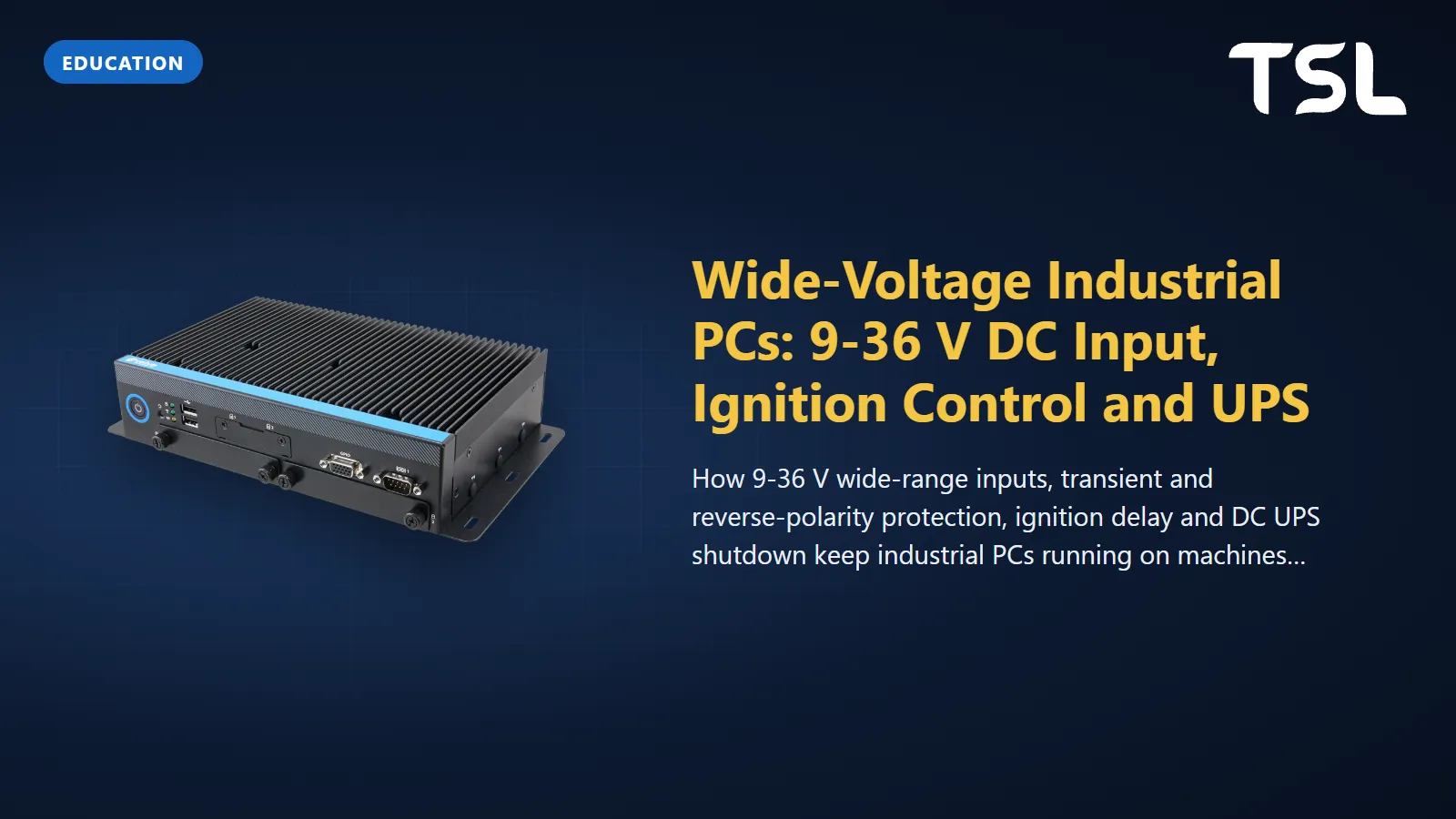
Table of Contents
A wide-voltage industrial PC accepts any DC supply inside a stated window, typically 9 to 36 V, so the same unit runs from a 24 V control cabinet, a 12 V van or a 24 V truck without a separate converter. On a vehicle that is only half the job: the PC also needs protection against the transients and reverse connections a vehicle supply produces, and an ignition input that starts it with the engine and shuts Windows or Linux down cleanly after the key is turned off. On a machine, the equivalent is a DC UPS that gives the PC time to close files before the 24 V rail drops.
12 V and 24 V systems: what the PC actually sees
Most machine control cabinets run on a regulated 24 V DC supply. Vehicles are less tidy. ISO's own summary of ISO 7637-2 describes its bench tests as applying to passenger cars and commercial vehicles fitted with 12 V or 24 V electrical systems, which is the split you meet in practice: 12 V on cars and light vehicles, 24 V on trucks, buses and much off-road equipment.
The voltage at the PC terminals is never the nominal figure. It sags when the engine cranks, rises while the alternator charges, and drops along thin cable. A wide-range input absorbs that spread: a 9 to 36 V window covers a 12 V system at its low end and a 24 V system at its high end, with margin on both sides. Not every device is that tolerant, which matters when you share one supply:
- The Cermate HMI panels we supply list 24 VDC ±10% (isolated) on their spec sheets. That suits a regulated cabinet supply, not a vehicle battery.
- Several current Avalue panel PCs list +12 V to +24 V. With no headroom above a nominal 24 V, feed them from a regulated supply.
- Models such as the ARC-10W33 10.1" panel PC list +9 V to +36 V with TVS surge protection and reverse current and voltage protection, so they suit displays mounted in the vehicle itself.
Transients, load dump and reverse polarity
A vehicle supply carries short, energetic disturbances on top of the slow sags and rises. Two ISO standards define how equipment is tested against them:
- ISO 7637-2:2011, "Electrical transient conduction along supply lines only", sets bench test methods for injecting and measuring conducted transients on equipment for 12 V and 24 V vehicles. ISO lists it as last reviewed and confirmed in 2025.
- ISO 16750-2:2023, "Electrical loads", the fifth edition, was published in July 2023. Its scope notes that electrical loads can vary with the resistance and inductance of the wiring harness, and that EMC is not covered.
The most destructive of these disturbances is load dump. Texas Instruments' application brief SNOAAA1 explains it as what happens when a battery is disconnected while the alternator is charging it and other loads are still connected. The load dump pulses are ISO 16750-2 Test A and Test B, previously designated 5a and 5b in ISO 7637-2. TI gives these typical values for the unsuppressed Test A pulse:
| Parameter (ISO 16750-2 Test A) | 12 V system | 24 V system |
|---|---|---|
| Peak voltage (Us) | 79 V to 101 V | 151 V to 202 V |
| Source resistance (Ri) | 0.5 Ω to 4 Ω | 1 Ω to 8 Ω |
| Pulse duration (td) | 40 ms to 400 ms | 100 ms to 350 ms |
The same brief notes that some vehicles have central load dump suppression clamping the surge to 35 V on 12 V systems and 58 V on 28 V systems, and that ISO 16750-2 requires equipment to withstand 10 consecutive pulses at one-minute intervals. So an input that ends at 36 V relies on the vehicle or an upstream protector to clamp load dump; a higher-rated input, such as the 9 to 60 V input of the VMS-RPPS, leaves more margin. And ask for the test report behind any "ISO 7637-2" line on a spec sheet: it states which pulses and severity levels were applied.
Reverse polarity is the other common failure: a battery connected backwards during service, or a swapped pair on a terminal block. Look for "reverse current/voltage protection" in the power section of the spec sheet. Among the models below, the VMS-EHLR, EMS-TGL and ARC-10W33 records list both TVS surge protection and reverse protection on the DC input, and the VMS-EHLR adds input isolation.
Ignition control: delay on, delay off
A PC wired straight to the battery either drains it overnight or loses power mid-write when the key is turned off. Ignition control solves both. The PC takes two feeds: a permanent, fused battery supply on V+ and a key-switched signal on the IGN input. In vehicle power mode:
- Key on: the IGN line rises and the PC powers up, usually after a short delay so it does not ride through the engine crank.
- Key off: the PC keeps running from the permanent feed for a set delay, so a short stop does not reboot it, then tells the operating system to shut down.
- Shutdown complete: the power controller cuts the PC off the battery so it draws nothing while parked. Many controllers also switch off if the battery falls below a threshold.
The delays are set in the power controller (by jumper, BIOS or utility, depending on the model), so confirm them in the unit's manual, and read the spec sheet wording closely. In our catalogue the VMS-RPPS lists "9~60Vdc Input, with Ignition Control & Vehicle Power Management", with vehicle power mode, industrial PC power mode or AT/ATX selected by jumper. The VMS-EHLR brings power in on an M12 A-coded connector whose four poles are V+, V-, GND and IGN, and its description names railways and public transport among its uses. The VMS-CFS and VMS-APL list vehicle power mode as their default setting, with an industrial PC (AT/ATX) mode as the alternative.
On a fixed machine you want the opposite behaviour: AT mode, where the PC switches on as soon as power appears, so it restarts by itself after a power cut. ATX mode waits for the power button. Several of the box PCs here, including the EMS-TGL, also have a 2-pin terminal block for wire-controlled power on/off, so a cabinet-door switch or a PLC output can start and stop the PC.
UPS and graceful shutdown on machines
Pulling 24 V from a running Windows PC risks a corrupted file system or a half-written recipe file. The fix is to keep the PC alive long enough to shut down, and tell it to:
| Approach | How it works | Good for | Watch out for |
|---|---|---|---|
| DC UPS module on the 24 V rail | Battery or capacitor module between the supply and the PC; a relay contact signals "mains lost" | Control cabinets, single PC plus HMI | Size it for the whole DC load it carries, not just the PC |
| Ignition control with off-delay | Vehicle battery is the reserve; IGN line triggers shutdown | Vehicles and mobile machines | Only covers key-off, not a cut battery cable |
The signal path is the part that gets forgotten. A UPS relay contact has to reach something the PC can read: a digital input on a GPIO header, a serial port handshake line, or the UPS vendor's USB link. The VMS-APL, for example, lists an 8-bit GPIO whose source-type digital inputs accept 0 to 30 VDC, so a 24 V signal switched by the UPS relay contact can be wired straight to one of them; a small service then watches that input and calls the operating system shutdown. Test it by switching off the supply with the application running, not by unplugging the UPS battery.
Power budgeting: size for the lowest voltage
A DC power budget is simple arithmetic, but it has to be done at the low end of the input range, because current rises as voltage falls (I = P / V). A 60 W PC draws 1.7 A at 36 V, 2.5 A at 24 V, 5 A at 12 V and 6.7 A at 9 V, so size cable, fuses and terminals for the sagging-battery case. Build the budget like this:
- PC maximum draw. If the spec sheet gives no consumption figure, use the adapter rating as a ceiling: the ARC-10W33 ships with a 60 W (12 V at 5 A) adapter. Measure the real figure with your application running at full load.
- Power the PC passes on. Some vehicle PCs feed other devices: the VMS-CFS lists a 12 Vdc/4 A DC output and the VMS-APL a 12 Vdc/6 A output. Whatever you hang on those, and on any PoE ports, comes out of your supply too.
- Everything else on the rail: displays, cameras, modems and HMIs.
- Inrush and margin. Several PCs switching on together from one ignition line can trip a fuse sized for steady current. Add headroom, and pick a supply or DC/DC converter that holds its output at the lowest input voltage you expect.
Wide-voltage and vehicle PCs compared
| Model | Type | DC input (spec sheet) | Ignition / power mode | Input protection listed | Certification listed |
|---|---|---|---|---|---|
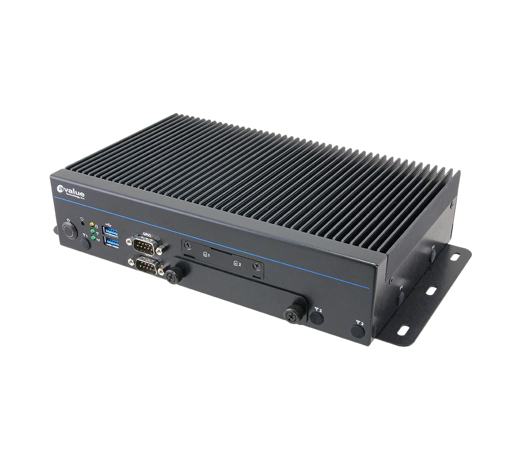
| VMS-RPPS | Transportation box PC, 13th Gen Intel Core | Typical 12/24/48 V (+9 to 60 V), 3-pin terminal block | Ignition control; vehicle / industrial / AT / ATX by jumper | Not stated in power rows | CE, FCC Class A, E24 Mark, ISO 7637-2, IP50 |
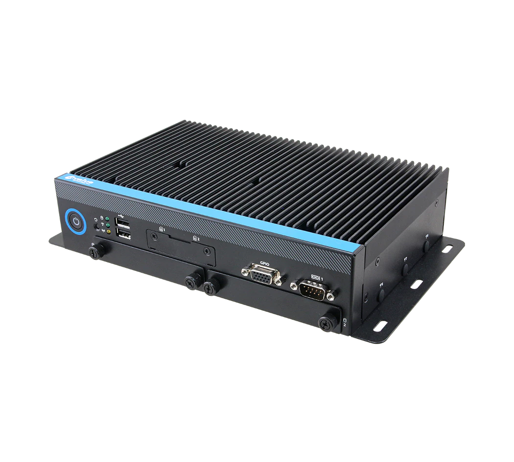
| VMS-EHLR | Vehicle box PC, Intel Atom x6425E | Typical 24 V (+9 to 36 V) with isolation, M12 A-coded | AT/ATX with ignition control | TVS surge, reverse current/voltage | CE, FCC Class A, UKCA, EN50155, EN50121, EN45545 |
| VMS-CFS | Vehicle box PC, 8th/9th Gen Intel Core | Typical 12/24 V (+9 to 36 V), 3-pin terminal block | Vehicle power mode (default) or AT/ATX | Not stated in power rows | CE, FCC Class A, E13 Mark, ISO 7637-2, IP50 |
| VMS-APL | Vehicle box PC, Intel Apollo Lake | Typical 12/24 V (+9 to 36 V), 3-pin terminal block | Vehicle power mode (default) or AT/ATX | Low voltage protection design | CE, FCC Class B, e13 Mark, ISO7637-2, IP50 |
| EMS-TGL | Modular box PC, 11th Gen Intel Core | Typical 12/24 V (+9 to 36 V), 3-pin terminal block | AT/ATX (ATX default), wire-control on/off | TVS surge, reverse current/voltage (max 13 A) | CE, FCC Class B, IP50 |
| ARC-10W33 | 10.1" fanless panel PC | +9 to 36 V, lockable DC jack or optional Phoenix connector | AT/ATX | TVS surge, reverse current/voltage | CE, FCC Class B |
For a road vehicle, start with the VMS-RPPS, VMS-CFS or VMS-APL, which list ISO 7637-2 and an E-mark. For rolling stock, the VMS-EHLR record lists EN50155. For a machine or AGV on a regulated 24 V rail, the EMS-TGL or the ARC-10W33 gives you the 9 to 36 V window without vehicle features you will not use. The VMS-APL and the ARC series have optional CAN bus kits; see our CAN bus explainer.
Installation checklist
- Measure the real supply range, including cranking and charging, before choosing the input range.
- Wire V+ to a permanent, fused battery feed and IGN to a key-switched feed.
- Set the power mode and on/off delays on the bench.
- Run the shutdown test: application running, supply or key off, check the logs on restart.
For the wider picture on vehicle computers (temperature, vibration and mounting), read our in-vehicle PC buying guide and the overview of Avalue transportation computers. If the PC is going on an AGV or AMR, see how to choose an AGV or AMR control PC.
How TSL can help
TSL Automation Solutions in Mumbai has been an authorised Avalue distributor since 2015 and ships worldwide. We can quote the VMS vehicle box PCs, the EMS modular box PCs and the wide-voltage ARC panel PCs, with full spec sheets for the models you shortlist. Narrow the range in the product finder and put two or three models side by side in the compare tool.
Send us the model numbers and quantities and we will reply with availability and lead time within one business day.
Frequently Asked Questions
TSL Automation Solutions
Head of Marketing, TSL Automation Solutions
Sanjana covers industrial automation trends, product launches, and technology insights for TSL Automation Solutions, a Mumbai-based distributor of HMI, Panel PC, and embedded computing systems serving manufacturers across India and globally.
Need help choosing the right product?
Our team in Mumbai can recommend the right HMI, Panel PC, or embedded system for your application.
Contact TSL Automation