
Section 12.5.1 · Chapter 12: Alarms and Alarm Displays
Analog Alarm Block - Settings
Use the dialog box to define all the settings for an analog alarm block. The following is an example of the analog alarm block dialog box.
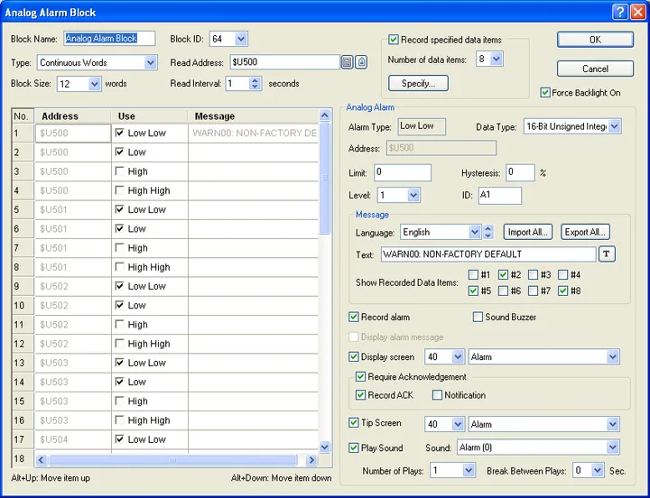
The table below describes each property in the Analog Alarm Block dialog box.
|
Property |
Description | ||
|---|---|---|---|
| Block Name | The analog alarm block's name. The maximum length of the name is 20 characters. | ||
| Block ID | The analog alarm block’s ID number. Select a number between 64 and 127. The number is unique among all analog alarm blocks of the panel application. | ||
| Type | Specifies the type of the analog alarm block. There are two types: | ||
| Type | Description | ||
| Continuous Words | Select Continuous Words to create an analog alarm block starting from the word device M with N continuous words | ||
| Random Words | Select Random Words to create an analog alarm block with N specified random words. | ||
| Legend: M: An address specified in Read Address field. N: A size specified in Block Size. | |||
| Read Address |
Specifies the starting address of an alarm block to
monitor the status of alarms. Click  to enter an address for this field. Click  to select a tag for this field. |
||
| Block Size | Specifies the block size of an alarm block. The unit is word. The maximum block size you can specify depends on the type you select. | ||
| Type | Maximum block size | ||
| Continuous Words | 16 | ||
| Random Words | 64 | ||
| Read Interval | Specifies a period between 1 to 3600 seconds that the panel reads the Alarm Block and checks the state of every bit in the block. The shorter the Read Interval is, the faster the alarm display object will be refreshed, but the refresh rate of other objects will be slower. | ||
| Record specified data items | <Check Box> | Check this option if you want to record the specified data values and display them in the alarm message. | |
| Number of data items | The number of data values you want to record. The maximum is 8. | ||
| Specify… | Click the button to specify the recorded data values. For details, please see Section 12.3.4 Specifying To-be-recorded Data. | ||
| Force Backlight On | Check this option so you can choose not to turn on the backlight automatically for the alarms of an alarm block. | ||
To specify all analog alarms, you need to set the analog
alarm list and the analog alarm properties field. The analog alarm list is
located at the bottom-left of the dialog, and shows all the analog alarms in the
alarm block. The analog alarm properties field is located to the right of the
list, and shows all the properties of the selected analog alarm.
The following table describes each column of the analog alarm
list.
|
Column |
Description |
|---|---|
| No. | The number of the analog alarm in the alarm block. |
| Address | Shows the address of the analog alarm. |
| Use | Check this option if you want to use analog alarm #n. |
| Message | Displays a specified alarm message in the selected language. To embed variable in the text of alarm message, please see 12.3.4. Specifying To-be-recorded Data.htm for details. |
You need to make a selection before editing the analog alarm.
To select an analog alarm, click the row of that alarm in the list. To select
multiple rows, click the row on its header column and use Ctrl + Click to add a
row to the selection.
If multiple rows are selected, any modification to the common properties such as
Level, Record alarm, Sound Buzzer, Display message, Display screen, Required
Acknowledgement, Record ACK, Notification, Tip Screen…will apply to all selected
analog alarms
The following table describes each column in the analog alarm list.
|
Property |
Description | ||
|---|---|---|---|
| Alarm Type | There are four types of analog alarms: | ||
| Type | Description | ||
| Low Low | An alarm will occur if the value of the destination variable is lower than or equal to the Low Low Limit. | ||
| Low | An alarm will occur if the value of the destination variable is equal to the Low Limit or between the Low Limit and the Low Low Limit. | ||
| High | An alarm will occur if the value of the destination variable is equal to the High Limit or between the High Limit and the High High Limit. | ||
| High High | An alarm will occur if the value of the destination variable is higher than or equal to the High High Limit. | ||
| Data Type | The data type of the destination variable. The supported data types include: 16-Bit Unsigned Integer, 32-Bit Unsigned Integer, 16-Bit Signed Integer, 32-Bit Signed Integer, 16-Bit BCD, 32-Bit BCD, 32-Bit Floating Point. | ||
| Address | Indicates the status of its corresponding alarm. | ||
| Type | Description | ||
| Continuous Words | Shows the address of the selected analog alarm. | ||
| Random Words |
Specifies the word variable of the selected analog
alarm. Click
to enter an address. Click
to select a tag. |
||
| Limit | Set a limit for the alarm. The value range of the limit depends on the specified data type. | ||
| Hysteresis | Set a range for the limit values for an alarm to turn OFF after it has been turned ON. If the alarm type is Low Low or Low, the range is between the Limit and Limit + Limit * Hysteresis/100. If the alarm type is High High or High, the range is between the Limit and Limit - Limit * Hysteresis/100. | ||
| Level | Select a level for the alarm between 1 and 8. | ||
| ID | Specifies the alarm ID. The maximum length of the ID is 6 characters. | ||
| Message | Language | Select an existing language that you are setting the message for. | |
| Import All… | Click the button to import the texts of *.csv files and saves the texts as the alarm messages for the current language. | ||
| Export All… | Click the button to export all the messages for the selected language to a *.csv file. | ||
| Text | Specifies the text for the current language. The text will be shown when the alarm is active. | ||
| Show Recorded Data Items | Check the specified value you want to record and display in the alarm message. Note that only the selected value will be recorded. | ||
| Record alarm | Check this option if you want to record the alarm in the alarm display object. | ||
| Sound Buzzer | Check this option if you want the panel to play a sound buzzer when the alarm is activated or cleared. | ||
| Display alarm message | Check this option if you want the panel to display a message automatically when the alarm is activated or cleared. This field can be checked only when Display screen is unchecked. | ||
| Display screen | <Check Box> | Check this option if you want the panel to display a window screen automatically when the alarm is activated or cleared. This field can be checked only when Display message is unchecked. | |
| Select a window screen to display when the alarm is activated or cleared. The field is available when Display Screen is selected. Note that only Window Screens will be available to choose from. | |||
| Required Acknowledgement | <Check Box> | Check this option if you want the operator to acknowledge an alarm. When an alarm becomes active, the panel displays an alarm message or a screen with ACK button when Required Acknowledgement is selected. The operator should press the ACK button to acknowledge the alarm and to have the panel refresh the current screen. This field is available when either Display message or Display screen is selected. | |
| Record ACK | Check this option if you want to record ACK in the alarm display object | ||
| Notification | Check this option if you want to notify the specified bit when the ACK button is clicked. | ||
| Bit | Specifies the bit that receives the notification. | ||
| Tip Screen | <Check Box> | Check this option if you want to display a screen when you select the corresponding alarm on the alarm display object. | |
| Select a window screen as the tip screen | |||
| Play Sound | <Check Box> | Check this option if you want the panel to play sound when the alarm is activated or cleared. | |
| Sound | Select a sound from sound table of the current panel application. | ||
| Number of Plays | Specifies how many times you want to play the sound. | ||
| Break Between Plays | Specifies an interval between two plays. You can select 0s, 0.2s, 0.4s, 0.6s, 0.8s, 1s, 2s, 3s, 4s, 5s. | ||
Need PM Designer itself?
V4 for current PK, PT, ITV and PM panels, V2 for older models. Free, sent by email.
Source.Section 12.5.1 of the PM Designer Software User Manual, Edition 2.0, © Cermate Technologies Inc. (www.cermate.com, service@cermate.com). Reproduced online, with the manual's own figures, by TSL Automation Solutions, authorised Cermate distributor, for users of Cermate HMI panels. PM Designer and PanelMaster are trademarks of Cermate Technologies Inc.
Text and figures are the manufacturer's and may describe features your panel or software version does not have. For a plain-language introduction read the PM Designer guide; for help with a specific panel contact TSL Automation.