
Chapter 7 of 13 · PM Designer guide
Alarms in PM Designer: alarm blocks, alarm displays and history
Alarms in PM Designer take three steps: set up alarm processing (the logging buffer and file saving), define one or more alarm blocks that tell the panel which PLC bits or words to watch and what message each one means, and place an alarm display on a screen to show the history, the active list, the counts or a scrolling marquee. A discrete alarm block watches bits, an analog alarm block watches word values against limits, and both can record process values with each alarm.
Applies to PM Designer V2.1 and V4.0Updated 11 Nov 2026Manual reference: Chapter 12
Step 1: set up alarm processing
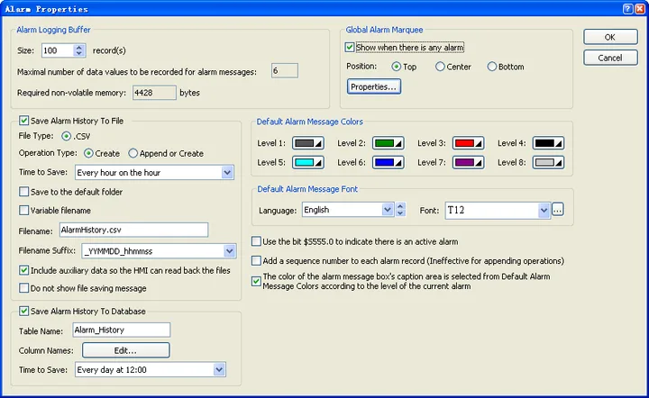
Double-click the Alarms node of the panel application to open Alarm Properties (Section 12.2). Here you size the alarm logging buffer in records: when it is full the oldest record is overwritten, and the buffer lives in battery-backed RAM, so 100 records cost 20 bytes each plus 4 bytes per recorded data value plus 28 bytes of overhead. The same dialog sets the default colour and font for alarm messages, configures a global alarm marquee that can scroll on every screen, and defines Save Alarm History To File: tick it and the panel appends every new record to a CSV (or XLS on the Windows runtime) at the interval you choose, in the default folder from General Setup or a path you name. Saving to file is what makes the history survive a flat battery and a download.
Step 2: create alarm blocks
Right-click the Alarms node and choose Add Discrete Alarm Block or Add Analog Alarm Block (Section 12.3.1). An application can have 64 of each. Blocks can be exported and imported as CSV, XML or ALM files, so a standard machine alarm list is written once and reused, and the CSV route lets the PLC programmer maintain the messages in a spreadsheet.
Discrete alarm blocks
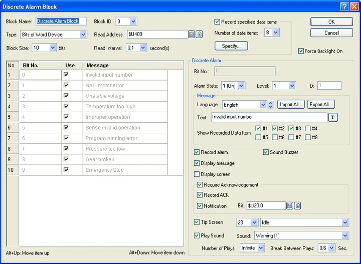
A discrete alarm block (Section 12.4.1) is tied to a Read Address and a Type that decides how the bits are found:
| Type | Watches | Maximum |
|---|---|---|
| Bits | N consecutive bits starting at a bit device | 256 bits |
| Bits of Word Device | N consecutive bits starting at bit 0 of a word device | 256 bits |
| Word Value | One word; the value 0 to N selects which alarm is active | Values 0 to 511 |
| Random Bits | N bits at addresses you list individually | 64 bits |
For each alarm you enter the message (per language), an alarm level, and options such as whether it needs acknowledgement, whether it opens a window screen when it occurs, whether it forces the backlight on and whether it sounds the buzzer. The Read Interval, 0.1 to 60 seconds, is how often the block is scanned; keep it long for slow processes, because every scan competes with screen updates for the link. "Bits of Word Device" is the usual choice with a PLC: reserve a word per 16 alarms, let the PLC set the bits, and the panel does the rest.
Analog alarm blocks
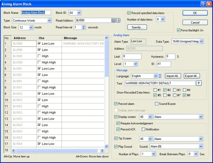
An analog alarm block (Section 12.5.1) reads up to 16 continuous words or 64 random words every 1 to 3600 seconds and raises an alarm when a value crosses a limit: high, low, high-high, low-low, or a deviation band around a set-point, each with its own message. Block IDs 64 to 127 are reserved for analog blocks, which is why a project's first analog block is number 64. Use an analog block for temperatures, pressures and levels that the PLC does not already turn into fault bits; use a discrete block when the PLC already evaluates the condition, which keeps the panel's scan light and the logic in one place.
Recording process values with an alarm
Both block types can record up to 8 data items with each alarm (Section 12.3.4): a name, an address, a data type and a display format. The values are captured at the moment the alarm occurs and appended to the message, for example "Dryer over temperature (Temperature: 123.4)". It is the cheapest form of root-cause data you can give a maintenance team, and it is also what the alarm logging buffer's size formula counts as data values.
Step 3: place alarm displays
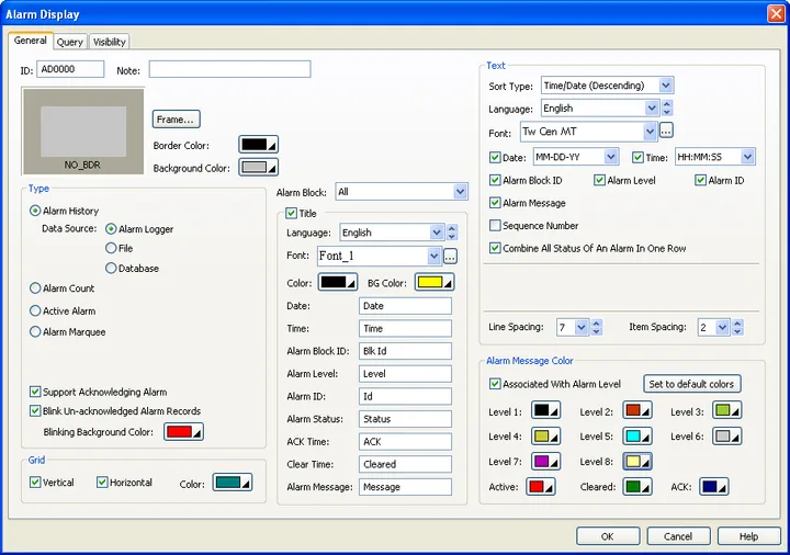
From the Object menu add an Alarm Display and choose its Type on the General page (Section 12.6.4):
- Alarm History: one row per record, with Active, ACK and CLR entries in different colours and optional columns for date, time, block ID, level, alarm ID, acknowledge time, clear time and message.
- Active Alarm: only the alarms that are on right now.
- Alarm Count: how many times each alarm has occurred.
- Alarm Marquee: the active messages scrolling horizontally in a single line, the right shape for the top of every screen.
The Data Source of a history display is the alarm logger (the live buffer) or a file buffer loaded from a CSV or TXT by a function button with the Load Logged Alarms From File operation, which is how an operator browses last month's history. Add Scroll Button Groups or a Scroll Bar next to a list to page through it, and a function button with Acknowledge Alarm or Acknowledge All to clear the ACK column. The Query page (Section 12.6.5) filters the rows: a static query is fixed at design time; a dynamic query reads a parameter block at runtime when a trigger bit goes on, so operators can filter by alarm number, date and time range, status or block from a small form on the screen.
Clearing and acknowledging from the PLC
The command block has flags for Clear Alarm History and Clear Alarm Counts (Chapter 4), and a Type A general command saves the logged alarms or alarm counts to a file on request. In a macro the equivalent file operations are available, and $S219 lets you refuse a clear from anyone below a given user level. Function buttons on the screen offer the same operations to the operator: Clear Alarm History, Clear Alarm Counts, Save Logged Alarms To File, Acknowledge.
Design notes from the field
- Number alarms by machine area and keep the message under about 40 characters so it fits a 7" marquee without scrolling twice.
- Set the discrete Read Interval to 1 second or more unless an alarm genuinely needs sub-second reaction; the PLC should handle anything faster.
- Give safety-related alarms a window screen (the Display Screen option) so they cannot be missed behind a trend page, and a level that requires acknowledgement.
- Tick Save Alarm History To File and point it at a USB stick or SD card on panels that have one, so the history outlives the battery and the next download.
- Export the finished blocks as CSV and keep the file with the project; it is the alarm list your customer will ask for.
Frequently asked questions
How many alarms can a PM Designer application have?
Up to 64 discrete alarm blocks of up to 256 bits each and 64 analog alarm blocks of up to 16 continuous or 64 random words. The alarm logging buffer size in Alarm Properties decides how many records are kept.
Why does my alarm history disappear after a download or a power cut?
The logging buffer is in battery-backed RAM. Tick Keep Previous Data > Alarm History in the Download dialog, and enable Save Alarm History To File in Alarm Properties so the records are also written to a CSV on the panel or a USB stick.
What is the difference between a discrete and an analog alarm block?
A discrete block watches bits (or a word value that selects an alarm) that the PLC sets. An analog block watches word values against high, low and deviation limits inside the panel. Use discrete when the PLC already evaluates the condition.
Can an alarm pop up a window?
Yes. In the alarm block settings tick the option to display a screen when the alarm occurs and choose a window screen; it opens over the current screen and can carry the acknowledge button.
Can the PLC clear the alarm history?
Yes. Enable the command block and use the Clear Alarm History and Clear Alarm Counts command flags, or let a function button on the screen do it for the operator.
Stuck on a Cermate panel?
TSL Automation has supplied and supported Cermate HMIs since 2015. Send us the model, the PM Designer version and a screenshot of the error.
Written by TSL Automation Solutions from the PM Designer user manual and application notes that ship with the software, and from our own support work. Screenshots are from the manual and remain the property of Cermate Technologies Inc. PM Designer and PanelMaster are trademarks of Cermate Technologies Inc. Check your panel's own manual for model-specific limits.