
Chapter 4 of 13 · PM Designer guide
Tags, internal memory and the command block in PM Designer
Every object and macro in PM Designer reads or writes an address. It is either internal memory on the panel ($U regular words, $N battery-backed words, $S system words, $I index registers) or a register on a PLC link written as link\address. Tags give those addresses names so a PLC change is a one-line edit, and the command block lets the PLC drive the panel: change screens, switch language, pick a recipe, clear alarms. This chapter covers all three.
Applies to PM Designer V2.1 and V4.0Updated 11 Nov 2026Manual reference: Sections 2.3, 3.3 and 3.6
Internal memory: $U, $N, $S, $I
The panel's own memory is addressed with a dollar sign and a letter (Section 3.3.1). A word is $U100; a bit inside it is $U100.5, with the bit number in hexadecimal 0 to f.
| Area | Address | What it is for |
|---|---|---|
| Regular user memory | $Un, $Un.b | Working storage: temporary values, screen state, macro variables. Cleared at power-up. Size set in the Internal Memory dialog, up to 131,072 words. |
| Battery-backed user memory | $Nn, $Nn.b | Values that must survive a power cycle: set-points, counters, machine configuration. Needs a panel with battery-backed RAM; the same 131,072-word limit. |
| System memory | $Sn | Maintained by the panel: clock, current user level, keypad buffer, language and more (below). Read it; do not write to it except where the manual says so. |
| Index registers | $I0 to $I63, $J0 to $J15 | 16-bit and 32-bit registers for indirect addressing. |
| Command block image | $CBn | A read-only copy of the command block words the panel last fetched. |
| Recipe memory | $Rm:n, $RNm | Word n of recipe block m, and the current recipe number of block m (see Chapter 8). |
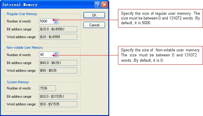
Set the size of $U and $N in the Internal Memory dialog under the Links node (Section 3.3.4). Keep $N as small as the job needs: battery-backed RAM is shared with recipe blocks, alarm logging and data loggers, and the compiler tells you when it runs out.
System words you will actually use
$S46to$S53: second, minute, hour, tenth of a second, day (0 = first), month (0 = January), year (0 to 99) and day of week (0 = Sunday) as binary values.$S42to$S45hold the same clock in BCD.$S219: the current user level, 0 to 9, where 9 means the developer password was used. Compare it in a macro to lock operations.$S0to$S25: the keypad input buffer, used by custom keypads.$S1039(V4): write a time-zone code here to change the panel's time zone at runtime (Chapter 12).
Index registers and indirect addressing
Put an index register inside square brackets and the address is computed at runtime (Section 3.3.2): W[$I30] is W2000 when $I30 holds 2000; $U[$I0+123] is $U223 when $I0 is 100; [$I2]:W100 addresses word 100 on the sub-link node held in $I2 (only $I0 to $I15 may be used for the node, without offset). One screen of "station n" objects can therefore show any station by changing $I2 in a macro or a word button. The software cannot check that the computed address exists, so bound the index yourself. Index registers are battery backed where the panel has that memory and are cleared when the application is updated.
PLC addresses
An address on a link uses the device's own notation: D100, MW70, 40001, DB10.DBW20. Without a prefix it refers to link 1; 2\D100 is D100 on link 2; 3:W100 is word 100 on sub-link node 3; 2\3:W100 combines both. The Address Input Keypad, opened by the small keypad icon next to any address field, lists only the register types the chosen driver supports, which is the quickest way to learn a driver's syntax. The manual explains the terms Write Address, Monitor Address, Read Address and Notification Bit in Section 4.4.3.1; the pattern is that buttons write, lamps monitor, displays read, and a notification bit lets the panel tell the PLC an operation finished.
Tags
A tag is a name for an address with a data type and a scan rate (Section 2.3). Use tags from the first day: an object bound to 1\MOTOR\Run_Cmd keeps working when the PLC address behind it changes, and the tag list doubles as the interface document between HMI and PLC programmer. The tags editor (Panel > Tags for local tags, Project > Global Tags for global ones) has a Tag Group Explorer on the left, where links, recipes and data loggers each own groups and sub-groups, and a tag list on the right with Name, Alias For, Data Type, Address, Scan Rate and Description columns.
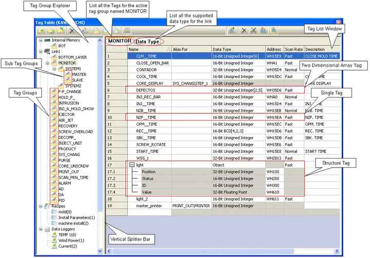
- Local tags belong to one panel application; global tags are shared by every application in the project, must start with an underscore (
_ALARM_SHOW) and can only point at internal memory. - Array tags name a contiguous block:
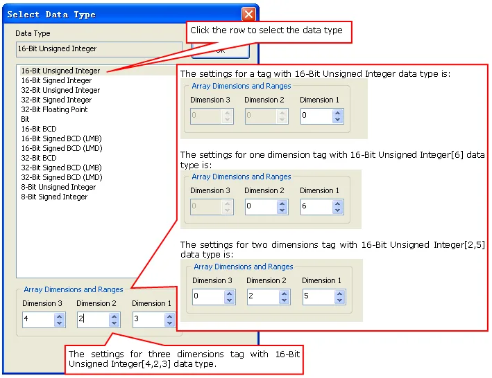
TANK[5]is the sixth element of a one-dimensional array,FLAG[1,2]and_Temp[1,0,2]address two- and three-dimensional ones. The element number is row times columns plus column, as the manual's examples show. - Structure tags hold several members of different types under one name:
Valve_1.Position. Structures are defined on the Data Type tab with continuous or random addressing and word or double-word alignment, and can be imported from a CSV. - Aliases let one address carry several names; the settings of an alias cannot differ from its tag.
- Names may be up to 48 characters, cannot start with a digit and cannot equal a macro keyword. Scan Rate is Fast or Normal; give Fast only to the handful of tags a screen must refresh quickly.
Tags import and export as tab-delimited CSV (right-click a link or group, Preview/Import Tags or Export Group), which is how a PLC symbol table becomes an HMI tag list in minutes. For Beckhoff, Allen-Bradley, CoDeSys, Mitsubishi, Omron EtherNet/IP and Panasonic controllers PM Designer can read the controller's own tag data types, and the OPC UA driver loads tags straight from the server.
The command block and status words
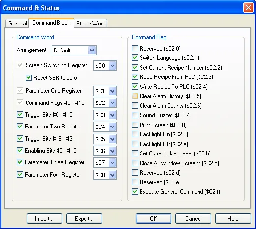
The command block is a block of words, in the PLC or in internal memory, that the panel scans every 0.25, 0.5 or 1 second and obeys (Section 3.6). The status words are words the panel writes back. Together they let the PLC program switch screens, change language, select a recipe, write a recipe to or from the PLC, clear the alarm history or counts, sound the buzzer, trigger event macros and save files, and let it know which screen, recipe, language and user level the panel is on. Open the Command & Status dialog from the Setup node of the panel application.
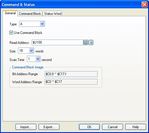
Type A is the choice for new projects. You tick only the words you need and the panel reads only those, in default or custom order: a Screen Switching Register, Parameter One to Three registers, a Command Flag Word with 16 flags, 32 trigger bits (each able to start an event macro or a data logger sample), 16 enabling bits and more. The status words report command flag acknowledgement, trigger acknowledgement, current screen number, current recipe block and number, current user level and current language. Type H packs screen number, language and backlight control into one word with fixed bit assignments and offers a binary or BCD flavour; it exists for compatibility with older projects.
Flag 15 of the Type A command word issues a general command (Section 3.6.7): put an operation code in Parameter One and a data ID in Parameter Two, raise the flag, and the panel saves logged data, alarms, counts, recipes or a screen print to a file with a default name such as DL3_date_time.csv. It is the simplest way to make the PLC archive data on a shift change without a macro.
Data types and display formats
Whatever the source, each object states how to interpret the word or words it reads: 16- or 32-bit signed or unsigned integer, 16- or 32-bit BCD, 32-bit floating point, byte array (ASCII string) or word array (double-byte string). Numeric objects add a display type (decimal, hexadecimal, octal, exponential, IP address) and scaling, so a 0 to 27648 analogue input can be shown as 0.0 to 100.0 percent without a macro. Get the data type wrong and the value is garbage; a 32-bit float read as a 16-bit integer is the classic case. Match the PLC programmer's declaration, and remember that a 32-bit value occupies two consecutive words.
Frequently asked questions
What is the difference between $U and $N memory in PM Designer?
$U is regular user memory, cleared when the panel powers up. $N is battery-backed user memory that keeps its values across a power cycle on panels that have battery-backed RAM. Use $N for set-points and anything the machine must remember.
How do I read the panel clock in a macro?
From the system words: $S46 second, $S47 minute, $S48 hour, $S50 day (0 = first), $S51 month (0 = January), $S52 year, $S53 day of week. $S42 to $S45 hold the same clock in BCD.
How does the PLC change the screen on the panel?
Enable the Screen Switching Register in the Command & Status dialog and have the PLC write the screen number to that word. The panel switches and, with Reset SSR to Zero ticked, clears the word.
Why must global tag names start with an underscore?
The underscore marks a tag as global in every panel application of the project. Local tag names cannot start with one, so the two namespaces never collide.
Can I import tags from my PLC program?
Yes. Export the PLC symbol table as CSV, right-click the link in the Tag Group Explorer and use Preview/Import Tags; the file is tab-delimited. Several controller families also let PM Designer read their tag data types directly, and the OPC UA client loads tags from the server.
Stuck on a Cermate panel?
TSL Automation has supplied and supported Cermate HMIs since 2015. Send us the model, the PM Designer version and a screenshot of the error.
Written by TSL Automation Solutions from the PM Designer user manual and application notes that ship with the software, and from our own support work. Screenshots are from the manual and remain the property of Cermate Technologies Inc. PM Designer and PanelMaster are trademarks of Cermate Technologies Inc. Check your panel's own manual for model-specific limits.