
Chapter 2 of 13 · PM Designer guide
PM Designer tutorial: your first HMI project from new file to running panel
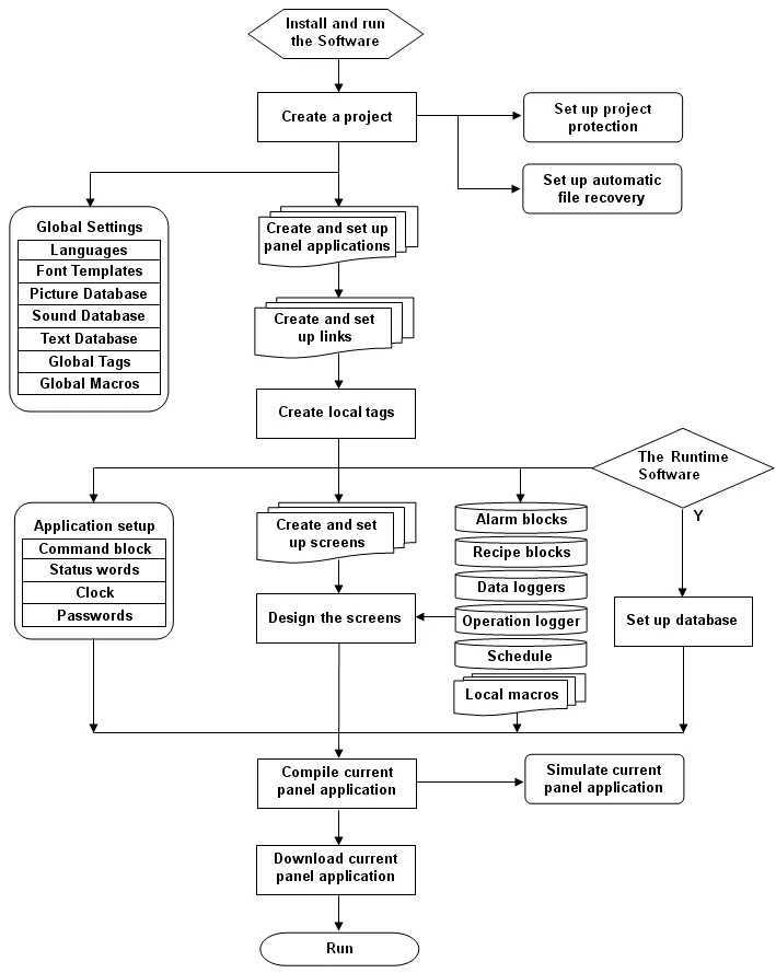
A PM Designer project goes from an empty file to a running panel in seven steps: create the project, add a panel application and pick the panel model, add a communication link to the PLC, draw a screen with a few objects, compile, test it in the simulator, and download it over USB or Ethernet. This tutorial builds a one-screen pump control page on a 7" PK2070 so you can follow every click.
Applies to PM Designer V2.1 and V4.0Updated 11 Nov 2026Manual reference: Chapters 1, 2, 3 and 18
Before you start
You need PM Designer installed (Chapter 1), the model number of your panel from the label on its back, and the PLC make and the port you will use to talk to it. For the walk-through we use a Cermate PK2070-31ST (sold by TSL as IPK2070-31ST), a Modbus RTU slave on COM2 and PM Designer V4; nothing changes for other models except the entries you pick in two dialogs. If you have no PLC on the bench yet, the project still works end to end because the off-line simulator provides virtual registers.
Step 1: create the project and a panel application
Choose File > New (Ctrl+N). PM Designer asks for a project name and location and then for the first panel application. A project is a container; a panel application is the thing that runs on one panel. Most projects have exactly one, but a project can hold up to 128, sharing global tags, pictures, fonts and macros, which is how a line with several identical panels is kept in one file.
In the New Panel Application dialog give the application a name and choose the Model. Click the browse button next to the model to open the Panel Model dialog, which lets you filter by display size, resolution and orientation. Pick the exact model, because the compiler builds the runtime for that hardware and the download is refused by a different panel. You can change the model later in General Setup if a project moves to a bigger screen; objects keep their pixel positions, so plan a short tidy-up afterwards.
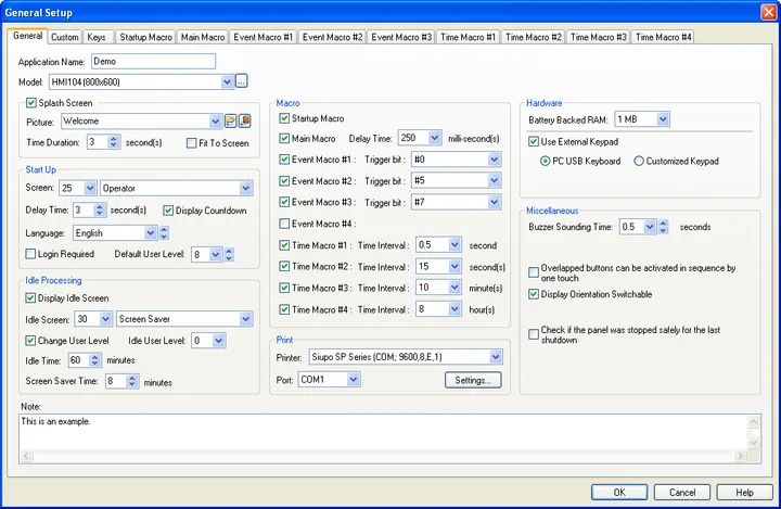
With the application created, open Panel > General Setup and check three settings on the General page: Start Up Screen (the screen the panel shows after power-up; we will create screen 1 shortly), Delay Time (how long the panel waits before running, 0 for now) and the Splash Screen if you want your logo while the application loads. Leave the Custom page alone for a first project.
Step 2: add the PLC link
In the Project Manager expand the panel application, right-click Links and choose Add Link. The Link Properties dialog opens on its General page. Set:
- Link Name: anything meaningful, for example "Modbus pump PLC".
- Link Type: Direct Link (COM) for a serial PLC, Direct Link (Ethernet) for a TCP connection.
- Device/Server: the maker and model of the PLC. For Modbus pick Modicon Corp and then the driver that matches your device's role; the manual's table in Section 3.4.9 explains which (the common choice for a slave PLC is "Modicon 984 Device/Slave (RTU)").
- Port: COM1, COM2 or COM3 for serial.
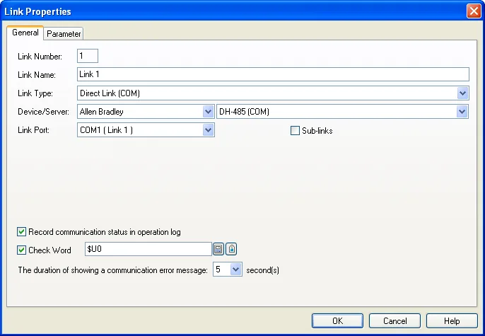
On the Parameter page enter the baud rate, data bits, parity, stop bits and the PLC's station address. The defaults for timeout, retry and command delay are fine for a first test. Click OK; the link appears under Links as Link 1. Every address you type from now on belongs to this link unless you prefix it with another link number (2\D100 means D100 on link 2). Chapter 3 goes into drivers, sub-links and Ethernet in detail.
Step 3: create a screen
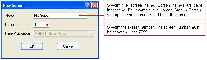
Choose Screen > New Screen (or right-click Screens in the Project Manager). Give it number 1 and the name "Pump control". Screen numbers and names must be unique within an application, and number 1 is the one we set as the start-up screen. The screen opens in the editor at the panel's native resolution, 800 x 480 for the PK2070. Set a background on the Screen Properties Background page if you like; a solid colour renders fastest.
Step 4: place three objects
From the Object menu (or the Object toolbar) add these, clicking on the screen to drop each one and double-clicking it to open its property sheet:
- Bit Button labelled "Pump 1 start". On its General page set Function to Set ON and Write Address to the PLC coil that starts the pump, for example
1\0(coil 1 on Modbus link 1); for a momentary push use Momentary ON instead. On the Label page type the text; on the Shape page choose a colour for each of the two states so the operator can see it change. - Bit Lamp labelled "Running", with Monitor Address pointing at the PLC's running-feedback bit. Give state 0 a grey shape and state 1 a green one.
- Numeric Entry for the set-point, with Write Address set to a holding register such as
40001, Data Type 16-Bit Unsigned Integer, 4 total digits, and a minimum and maximum so the operator cannot type an unsafe value. Touching it on the panel pops up the built-in numeric keypad; no extra programming is needed.
Use Edit > Align and Make Same Size to line the objects up, and press the Off (State 0) and On (State 1) toolbar buttons to preview both states of every object on the screen. Save the project (Ctrl+S). Chapter 5 covers every object type; for now three are enough to prove the chain from touch to PLC and back.
Step 5: compile
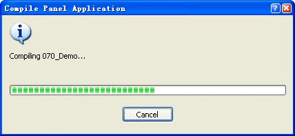
Choose Panel > Compile or click the Compile icon on the toolbar. The Compile Panel Application dialog reports errors and warnings and, on success, the size of the runtime data. Errors appear in the Build List window at the bottom of the workspace; double-click one to jump to the object or macro it refers to. Typical first-project errors are an address that is outside the driver's range and a start-up screen that does not exist. Fix and compile again until the count is zero. Warnings about unused tags can be ignored.
Step 6: simulate on the PC
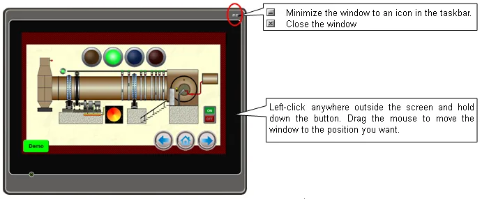
Choose Tools > Run Off-line Simulation. A window the size of the panel appears and runs your compiled application against virtual registers held in PC memory. Click the start button and the lamp will not light, because nothing drives the feedback bit; that is expected. Click the numeric entry, type a value on the keypad and press Ent: the value is written to the virtual register and read back into the display, which proves the object is configured correctly. Off-line simulation never produces a communication error, which is exactly why it is the right tool for checking screens and logic before the hardware exists.
If the PLC is on the bench and connected to the PC's serial port, Tools > Run On-line Simulation talks to it for real and is the quickest way to prove the link parameters before touching the panel. Chapter 11 compares the two modes.
Step 7: download to the panel
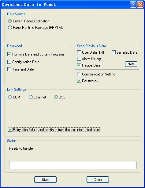
Connect the panel with a USB cable (or set its IP address in Panel Setup and connect it to the network) and power it. Choose Panel > Download. In the Download Data to Panel dialog keep Data Source on the current panel application, tick Runtime Data and System Programs, choose USB (or Ethernet and the panel's IP address) under Link Settings, and click Start. A modified application is compiled automatically before the transfer. The first download to a new panel takes a few minutes because the system programs go with it; later downloads of the application alone are much faster.
If the panel prompts for a developer password it is because it holds a project with a different password; a new panel accepts the default 000000000 without asking. When the transfer ends the panel restarts into your start-up screen. Press "Pump 1 start": the PLC coil goes on, the feedback bit returns and the lamp turns green. Your first PM Designer project is running.
What to do next
- Replace raw addresses with tags so that a PLC change is a one-line edit (Chapter 4).
- Add a window screen for a settings pop-up and a screen button to open it (Chapter 5).
- Define an alarm block on the PLC's fault bits and drop an alarm display on a second screen (Chapter 7).
- Set the developer password in Project > Information & Protection before the panel leaves the workshop, and write it down; the panel asks for it before it accepts any other project.
Frequently asked questions
The panel refuses the download and says the model does not match. Why?
The project is compiled for a different panel model. Open Panel > General Setup, choose the exact model printed on the back label (for example PK2070-31ST, listed by TSL as IPK2070-31ST), recompile and download again.
Do I need a PLC to try PM Designer?
No. The off-line simulator creates virtual registers for every address in the project, so screens, buttons, entries, alarms and macros can all be tested on the PC with nothing connected.
Where do I set the first screen the panel shows?
In Panel > General Setup, General page, Start Up Screen. The screen must exist and be a normal screen.
Stuck on a Cermate panel?
TSL Automation has supplied and supported Cermate HMIs since 2015. Send us the model, the PM Designer version and a screenshot of the error.
Written by TSL Automation Solutions from the PM Designer user manual and application notes that ship with the software, and from our own support work. Screenshots are from the manual and remain the property of Cermate Technologies Inc. PM Designer and PanelMaster are trademarks of Cermate Technologies Inc. Check your panel's own manual for model-specific limits.