
Chapter 3 of 13 · PM Designer guide
PLC communication in PM Designer: links, drivers and addressing
A PM Designer panel talks to a PLC through a communication link: you add a link, choose Direct Link (COM) or Direct Link (Ethernet), pick the device driver for your PLC, and set the port parameters or IP address. Every address in the project then refers to that link. This chapter explains the link types, how to choose a Modbus driver, the Siemens S7 settings that trip people up, sub-links for multi-drop networks, and how to read the link status from a macro when something goes wrong.
Applies to PM Designer V2.1 and V4.0Updated 11 Nov 2026Manual reference: Section 3.4, application note s7-ethernet-driver
Types of communication link
A panel application can have 4 or 16 links depending on the model, and each is one of three kinds (Section 3.4.1):
- Direct link: the panel is wired to the device, by RS-232, RS-485 or Ethernet. This is what almost every project uses. An RS-485 or Ethernet direct link can carry several slave devices as sub-links.
- Indirect link: the panel reaches a device through another panel that is directly connected to it, the "2-to-1" and "N-to-1" arrangements where one PLC port serves several HMIs.
- Communication service: the panel offers something to others: a 2-to-1 or N-to-1 server, a transparent server that lets a PC's programming software reach the PLC through the panel, a gateway server that exposes the panel's memory and its PLCs as Modbus registers, or a Data Sharer that broadcasts up to 256 words to as many as 16 panels on a network.
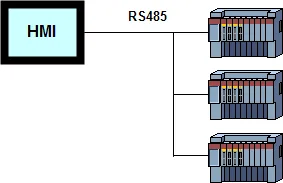
Adding a link: the General page
Right-click Links in the Project Manager and choose Add Link, or use Panel > Link > Add. On the General page of Link Properties (Section 3.4.2) set the link name, the Link Type and the Device/Server. The device list is grouped by manufacturer: Siemens, Mitsubishi, Omron, Allen-Bradley, Delta, Schneider/Modicon, Beckhoff, CoDeSys, Panasonic and many more, each with one driver per protocol or port type. The link is numbered when created; link numbers shift down if an earlier link is deleted, so add links in a sensible order and leave them in place.
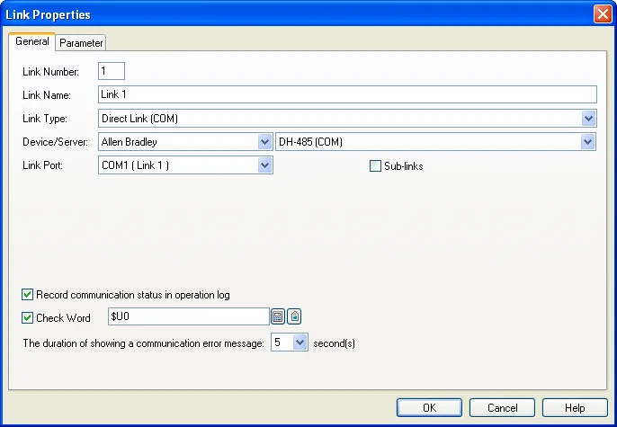
Serial parameters
For a COM link the Parameter page (Section 3.4.3) holds baud rate, data bits, parity, stop bits, the Panel Address (the panel's own station number, used by protocols that need one) and the PLC Address (the station number of the device). Three timing values decide how the driver behaves when the device is slow or absent:
| Setting | Meaning | Advice |
|---|---|---|
| Timeout Time | How long the driver waits for a reply before declaring the request failed. | Raise it for slow devices or long RS-485 runs; lower it when a missing slave must not slow the screen. |
| Retry Count | Attempts per request before the link is flagged in error. Zero means the driver default. | Two or three is typical. Many retries make a dead slave freeze other links' updates. |
| Command Delay | Pause between the reply of one request and the next request. | Zero for most PLCs; a few milliseconds for devices that cannot turn an RS-485 line around quickly. |
The same page also controls fetching data in blocks: the driver merges adjacent reads into block reads to refresh screens faster. Disable it for the rare PLC that cannot do block reads, or adjust the block-forming criteria if a device limits the span of a single read.
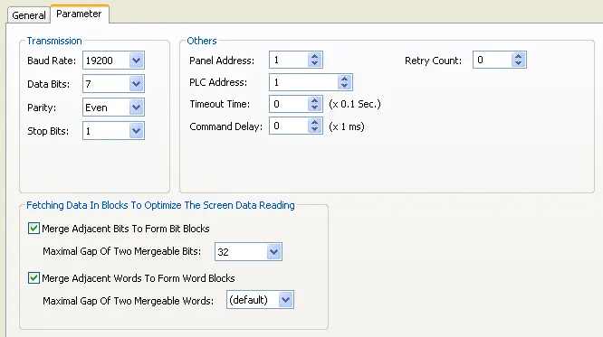
Ethernet parameters
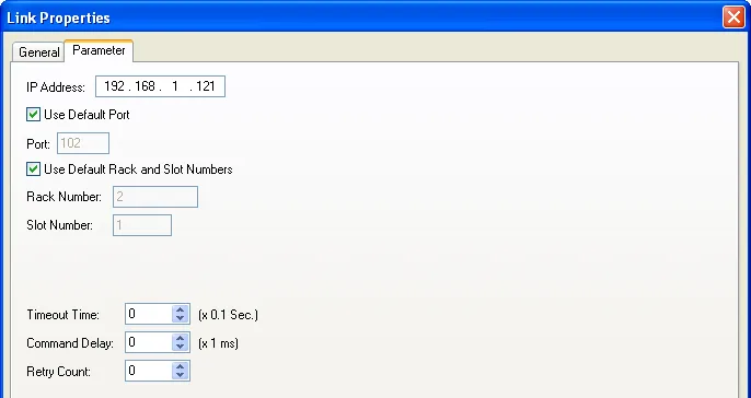
For an Ethernet link the Parameter page (Section 3.4.4) asks for the device's IP address, the port (tick Use Default Port unless the PLC was configured otherwise), the node address where the protocol needs one, and the same timeout, command delay and retry values. The panel's own IP address is not set here: it belongs to the panel and is entered in its Panel Setup screen, or written at runtime with the LINK_PAR macro. The PC running on-line simulation uses its own address.
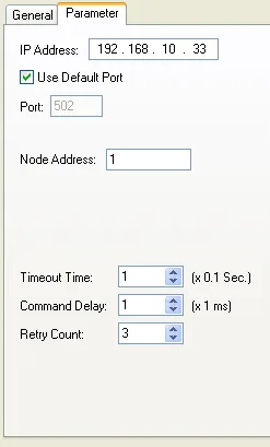
Sub-links for RS-485 and Ethernet networks
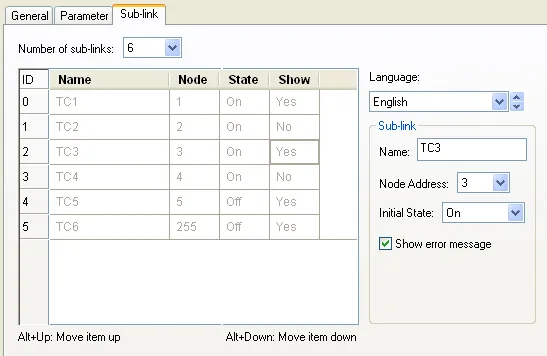
When one link talks to several slaves, the Sub-link page (Section 3.4.5) defines them: how many, the name of each (per language, because an operator can see it in a Sub-link Table object), the node address or IP address, the initial state (On or Off) and whether communication errors on that sub-link show a message. A sub-link that is Off at start is not polled until a sub-link table or the EN_LINK macro turns it on, which is how a project copes with a machine whose optional modules are not always fitted. Addresses on a sub-link are written as node:address, for example 3:W100 for word 100 on node 3.
Choosing a Modbus driver
The Modbus drivers are listed under Modicon Corp. and the names say which end the panel is (Section 3.4.9). Read them as follows:
- "Device/Slave" in the name: the connected device is the slave; the panel is the master and polls it. This is the normal case for a PLC, drive or temperature controller. Choose RTU, ASCII or TCP to match the device, and "Quantum" (driver C2C081) if you need addresses above 9999 or want to use hexadecimal addressing.
- "Master" in the name: the connected device is the master and the panel is the slave answering it. Use this when a PLC or SCADA writes into the panel. The "Non-volatile slave data" variant keeps the slave data in battery-backed RAM.
Address ranges follow the Modbus convention: 1 to 9999 and 10001 to 19999 are bits, 30001 to 39999 and 40001 to 49999 are words. Because a plain number like 40001 could be an address or a constant in a macro, add a K suffix (40001K) when you mean the number.
A Gateway Service link (Section 3.4.8) turns the panel into a Modbus TCP or RTU server for a PC: an address mapping table maps blocks of the panel's $U and $N memory and of any PLC on its other links into Modbus coil and register ranges, so SCADA can read a Siemens or Mitsubishi PLC through the panel without a protocol converter.
Siemens S7 over Ethernet
Select Siemens AG and the SIMATIC S7 Ethernet driver, enter the CPU's IP address, and then the two settings that cause most support calls (Section 3.4.11 and the s7-ethernet-driver application note): the Rack and Slot numbers must match the hardware configuration (slot 1 for S7-1200 and S7-1500, usually slot 2 for S7-300), and every data block the panel reads must have "Symbolic access only" (TIA Portal calls it optimized block access) unchecked, or the panel shows a communication error on every object that touches that block. The driver supports indexed data block addressing such as DB[$I3].DBW100, so one screen can show the same structure from different DBs by changing an index register.
OPC UA
V4 includes an OPC UA client driver (Section 3.4.12): choose OPC Link as the type, discover servers on the local machine or a named host, test the connection with or without a user name, then browse the server's address space and load the nodes you want as tags. Scalars and one- or two-dimensional arrays of the common integer, float, boolean and string types are supported. It runs on the HMI runtime for Windows and on panels with the newer operating system; Chapter 12 has more.
Reading the link status from a macro
Objects show a communication error on screen, but a macro can read the state of a link or sub-link with LINK_STS and act on it, for example by switching a lamp or disabling the sub-link with EN_LINK until an operator clears it. The status values (Section 15.4.13) are:
| Value | Meaning | Value | Meaning |
|---|---|---|---|
| 0 | OK | 13 | Invalid request |
| 1 | Overrun error | 14 | Device busy |
| 2 | Break error | 15 | Unknown error |
| 3 | Parity error | 16 | Link disabled |
| 4 | Framing error | 17 | Initialization failure |
| 5 | No response | 18 | Failed to send data |
| 6 | Unrecognized response | 19 | Failed to receive data |
| 7 | Timeout | 20 | Failed to open connection |
| 8 | Inactive CTS | 21 | Connection not ready |
| 9 | Checksum error | 22 | Invalid sub-link |
| 10 | Command rejected | 23 | Invalid COM port |
| 11 | Invalid address | 24 | Error |
| 12 | Invalid range | 255 / 65535 | Condition uncertain / failed to get status |
$U100 = LINK_STS(1, 0)      // status of link 1 (no sub-link)
IF $U100 == 5 (U)            // no response: PLC off or cable
   $U0.0 = 1 (B)             // light the "PLC offline" lamp
ELSE
   $U0.0 = 0 (B)
ENDIF
EN_LINK(1, 20, 0)            // stop polling sub-link node 20 of link 1
Values 3, 4 and 9 point at wrong serial parameters or a noisy line; 5 and 7 at wiring, power or a wrong station address; 11 and 12 at an object whose address the device does not have; 20 and 21 at IP, port or firewall problems on Ethernet.
Talking to a device without a driver
When no driver exists, select PanelMaster General Device (COM) and write the protocol in a macro (Section 3.4.7). The link exposes keywords for the serial port: write a block of words to TX to transmit, read received bytes from the receive buffer, and use the status words to pace the exchange. It is work, but it makes barcode readers, scales and instruments with simple ASCII protocols usable, and TSL can advise on whether a dedicated driver is available on request. V4 also adds a CANbus driver built on the same generic-device idea (Chapter 12).
Frequently asked questions
Which Modbus driver do I pick for a PLC that is a Modbus slave?
One of the Device/Slave drivers under Modicon Corp.: RTU or ASCII for serial, TCP for Ethernet. Use the Quantum variant for addresses above 9999. The panel is then the Modbus master.
Why does my Siemens S7 link show a communication error although the IP address is right?
Check the rack and slot numbers on the Parameter page and make sure every data block the panel reads has "Symbolic access only" (optimized block access) unchecked in the PLC project.
How many PLCs can one Cermate panel talk to?
Up to 4 or 16 links depending on the model, and an RS-485 or Ethernet link can carry many slaves as sub-links, each with its own node address.
Where do I set the panel own IP address?
On the panel: Panel Setup > General (IP address, subnet mask, gateway). The Link Properties dialog only holds the address of the device the panel connects to.
How do I address a register on a second link?
Prefix the address with the link number and a backslash, for example 2\D100 for D100 on link 2, and with the node for a sub-link, for example 3:W100.
Stuck on a Cermate panel?
TSL Automation has supplied and supported Cermate HMIs since 2015. Send us the model, the PM Designer version and a screenshot of the error.
Written by TSL Automation Solutions from the PM Designer user manual and application notes that ship with the software, and from our own support work. Screenshots are from the manual and remain the property of Cermate Technologies Inc. PM Designer and PanelMaster are trademarks of Cermate Technologies Inc. Check your panel's own manual for model-specific limits.