
Section 9.6.5 · Chapter 9: Animated Objects
Animated Graphic - Path Settings
This section describes how to define the path settings for animated graphics. You can easily define the path of an animated graphic in the editing window. To edit the path of an animated graphic, click it to display the path as shown in the following example.
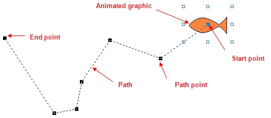
To modify the path, drag the path points to desired positions. You can insert a path point by right-clicking at the desired position on the path and clicking Insert Point from the popup menu. To delete a path point, right-click at the path point and click Delete Point on the popup menu. Use the Path page to define all the properties of the path.
The following is an example of the Path page.
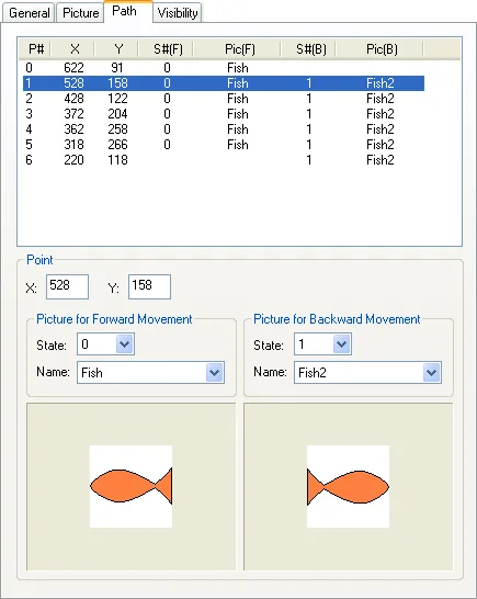
The following table describes each property in the Path page.
|
Property |
Description | |
|---|---|---|
| X | The horizontal coordinate of the selected path point. | |
| Y | The vertical coordinate of the selected path point. | |
| Picture for Forward Movement | State | The associated state of the selected path point for forward movement. |
| Name | The associated picture name of the selected state. It is also the associated picture name of the selected path point for forward movement. | |
| Picture for Backward Movement | State | The associated state of the selected path point for backward movement. |
| Name | The associated picture name of the selected state. It is also the associated picture name of the selected path point for backward movement. | |
Need PM Designer itself?
V4 for current PK, PT, ITV and PM panels, V2 for older models. Free, sent by email.
Source.Section 9.6.5 of the PM Designer Software User Manual, Edition 2.0, © Cermate Technologies Inc. (www.cermate.com, service@cermate.com). Reproduced online, with the manual's own figures, by TSL Automation Solutions, authorised Cermate distributor, for users of Cermate HMI panels. PM Designer and PanelMaster are trademarks of Cermate Technologies Inc.
Text and figures are the manufacturer's and may describe features your panel or software version does not have. For a plain-language introduction read the PM Designer guide; for help with a specific panel contact TSL Automation.