
Section 9.7.3 · Chapter 9: Animated Objects
Path Display - General Settings
This section describes how to define the general settings for path display. The following is an example of the General page of the Path Display property sheet.
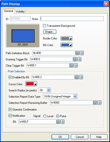
The following table describes each property in the General page.
|
Item |
Description | |||||
|---|---|---|---|---|---|---|
| ID | The object’s identifier. It is generated when the object is created. The identifier is unique within the screen where the object is located. The format of the IDs for the path display is DPnnnn. | |||||
| Note | You can type a note for the object. | |||||
| Transparent Background | Select this option if you want the object to have a transparent background. | |||||
| Shape settings |
For details about the following properties, see
Section 4.3.4 Setting up the
Shape of an Object.
 ,
Border Color, BG Color |
|||||
| Path Definition Block |
The starting address of an internal memory block that stores the data of how to draw the path.
Click
 to enter an address for this field. Click  to select a tag for this field. The data are arranged in the following format: |
|||||
| Word No. | Description | |||||
| 0 | Number of path elements in the path | |||||
| 1~8 | The definition of the first path element | |||||
| 9~16 | The definition of the second path element | |||||
| … | … | |||||
| (8n-7)~8n | The definition of the nth path element | |||||
|
See Section 9.7.3.1 Definitions of Path Elements to know how to define path elements. The path elements include: points, lines, arcs, and circles. See Section 9.7.3.2 Color Values to know how to specify colors for path elements. |
||||||
| Drawing Trigger Bit |
The bit or the word's bit that triggers the object to draw the path
defined in the Path Definition Block. Click
to enter an address for this field. Click
to select a tag for this field. A 0 to 1
transition of the bit generates a valid trigger, so you
should reset the bit to 0 before issuing next trigger. The object will copy the path definition from the Path Definition Block to its local memory so it can redraw the path later even the data in Path Definition Block changes. |
|||||
| Clear Trigger Bit |
The bit or the word's bit that triggers the object to erase the path it
has drawn. Click
to enter an address for this field. Click
to select a tag for this field. A 0 to 1 transition of the bit generates a
valid trigger, so you should reset the bit to 0 before
issuing next trigger. The path definition in the object’s local memory is erased too. |
|||||
| Point Selection | Enabled By Bit |
Select the option if you want to enable and disable the
point selection capability by a bit.
Specify a bit when the option is selected. Click
to enter an address for this field. Click
to select a tag for this field. |
||||
| Cursor Color | The color of the cursor that helps the operator to locate a point. | |||||
| Search Radius | The path display will find the closest point to the current cursor position within the search circle as the selected point. The center of the search circle is at the current cursor position and the radius is the Search Radius specified here. | |||||
| Selection Report Data Type | The following table describes the structure of the report data when “16-bit Unsigned Integer” is selected. | |||||
| Word No. | Description | |||||
| 0 | The x-coordinate of the selected point | |||||
| 1 | The y-coordinate of the selected point | |||||
| 2 | The sequence number of the point element where the selected point is on | |||||
| 3 | The type of the selected point. The following table describes its value and meaning. | |||||
| Value | Meaning | |||||
| 0 | The point of a point, the center of a circle, the starting point of a line, or the starting point of an arc. | |||||
| 1 | The ending point of a line or the ending point of an arc. | |||||
| Selection Report Receiving Buffer |
The starting address of a word memory block that will
receive the information of the selected point. Click
to enter an address for this field. Click
to select a tag for this field. |
|||||
| Operator Confirmation | Select the option if the operator confirmation is required before reporting the point selection. | |||||
| Notification | <Check Box> | Select the option if notifying a bit is required before reporting the point selection. | ||||
| Signal | Select one of the following signals for the notification: | |||||
| Signal | Description | |||||
| Level | Set the specified bit to the specified state. | |||||
| Pulse | Send a positive pulse to the specified bit. | |||||
| Bit |
Available when the Notification field is checked.
Specifies the bit for the operation done notification.
Click
to enter an address for this field. Click
to select a tag for this field. |
|||||
In this section
Need PM Designer itself?
V4 for current PK, PT, ITV and PM panels, V2 for older models. Free, sent by email.
Source.Section 9.7.3 of the PM Designer Software User Manual, Edition 2.0, © Cermate Technologies Inc. (www.cermate.com, service@cermate.com). Reproduced online, with the manual's own figures, by TSL Automation Solutions, authorised Cermate distributor, for users of Cermate HMI panels. PM Designer and PanelMaster are trademarks of Cermate Technologies Inc.
Text and figures are the manufacturer's and may describe features your panel or software version does not have. For a plain-language introduction read the PM Designer guide; for help with a specific panel contact TSL Automation.