
Section 9.1.1 · Chapter 9: Animated Objects
Pipeline - Basic Operations
A pipeline is composed of L/T/Cross connectors and pipes. With the software, you can create a pipeline easily and efficiently. You can also control a pipeline to change color, blink, and/or show the flow effect dynamically at runtime.
The following is a sample of a pipeline with the flow effect:
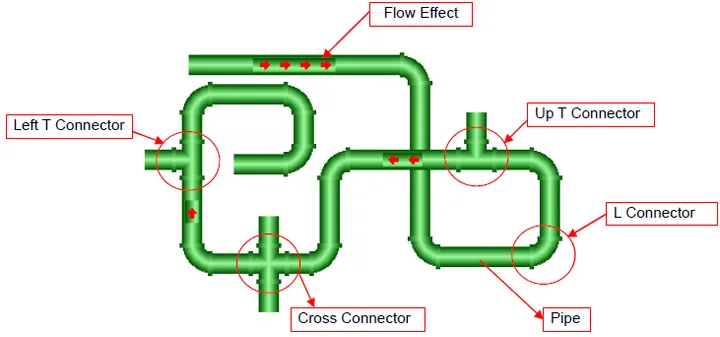
To draw a pipeline, you need to do the following:
- In the Object menu or Object toolbar, click Pipeline
 to draw a pipeline.
- Move the cursor onto the screen where you want to draw a pipeline and click the position for the start point of the pipeline.
- Continue clicking on the screen to place as many L connectors needed for the pipes in the pipeline.
- Right-click to complete the pipeline.
- Drag one blue handle on the boundary of the pipeline at a time to resize the pipeline.
- Drag one blue or black handle on the pipeline at a time to adjust the position and length of the selected pipe of the pipeline. The pipe or connector with black handles represents the selected pipe or connector.
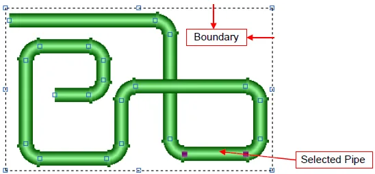 |
The picture on the left shows the handles of a
pipeline. The blue handles on the boundary of the
pipeline are for resizing the entire pipeline. The blue
or black handles on the pipeline are for moving the
vertices of the selected pipe. Position the mouse pointer over one of the handles. When the cursor changes to  or  or  or  drag the handle until the pipeline is the shape and size
you want. |
-
Right-click anywhere on the pipeline and use the Insert Connector command on the object pop-up menu to insert a new T/ Cross connector to the pipeline. Alternatively, right-click the existing connector or pipe of the pipeline and use the Delete Pipe Segment command on the object pop-up menu to delete the connector and its connected pipe.
|
Pop-up menu |
Description |
|---|---|
| Insert Connector |
Add an Up/Down T or Cross connector to the specified
position on the horizontal pipe.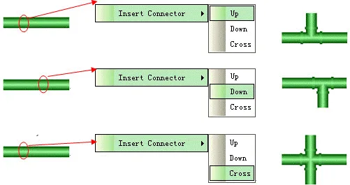 Add a Left/Right T or Cross connector to the specified position on the vertical pipe 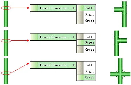 |
| Delete Pipe Segment |
Delete a selected pipe segment and its successor.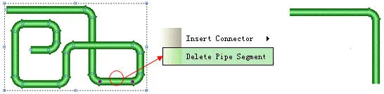 |
You can complete all the settings of a pipeline in the Pipeline property sheet. This sheet contains the following three pages.
■ General
Described in Section 9.1.4.
■ Pipe
Described in
Section
9.1.5.
■ Visibility
Described in
Section
4.4.6.
Need PM Designer itself?
V4 for current PK, PT, ITV and PM panels, V2 for older models. Free, sent by email.
Source.Section 9.1.1 of the PM Designer Software User Manual, Edition 2.0, © Cermate Technologies Inc. (www.cermate.com, service@cermate.com). Reproduced online, with the manual's own figures, by TSL Automation Solutions, authorised Cermate distributor, for users of Cermate HMI panels. PM Designer and PanelMaster are trademarks of Cermate Technologies Inc.
Text and figures are the manufacturer's and may describe features your panel or software version does not have. For a plain-language introduction read the PM Designer guide; for help with a specific panel contact TSL Automation.