
Section 9.7.4 · Chapter 9: Animated Objects
Path Display for Rebar Bending Machine
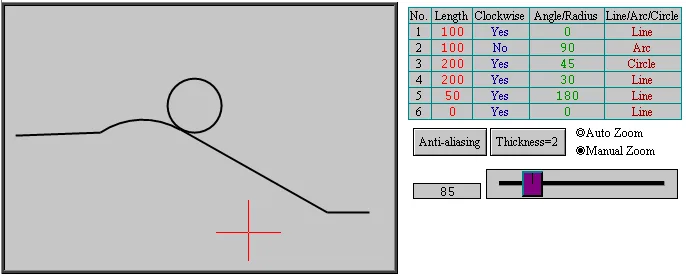
A path display can be used to visualize the bending result of the rebar bending machine. The following is an example of the application:
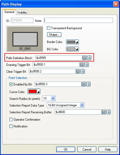
■ Creating a path display
■ Making Bending Parameters Block
The user is allowed to bend max 32 segments for one piece of rebar. The following table describes the memory map of bending parameters:
| Bending Parameters | Segment No. | Word No. | Example(SegPar @$U100) | Remark |
|---|---|---|---|---|
| Length of segment | 1 | 0 | $U100 | |
| 2 | 2 | $U102 | ||
| ... | ... | ... | ||
| 32 | 62 | $U162 | ||
| Angle/Radius of segment | 1 | 64 | $U164 | |
| 2 | 66 | $U166 | ||
| ... | ... | ... | ||
| 32 | 126 | $U226 | ||
| Direction of segment | 1 | 128.0 | $U228.0 |
0: Clockwise 1: Counter Clockwise |
| 2 | 128.1 | $U228.1 | ||
| ... | ... | ... | ||
| 32 | 129.f | $U229.f | ||
| Shape of segment | 1 | 130 | $U230 |
0: Line 1: Arc 2: Circle |
| 2 | 132 | $U232 | ||
| ... | ... | |||
| 32 | 192 | $U292 |
■ Making Visualization Preprocess Request Block
The following table describes the memory map of visualization preprocess request block.
| Word No. | Example (@$U300) | Description |
|---|---|---|
| 0 | $U300 |
Bit 0 1: Enable the anti-aliasing drawing feature Bit 1-15 Reserved |
| 1 | $U301 | Thickness of the lines to be shown. Valid numbers: 1 to 5 |
| 2 | $U302 | The width of the associated Path Display |
| 3 | $U303 | The height of the associated Path Display |
| 4 | $U304 | 0: Auto Scaling; 1: Manual Scaling; |
| 5 | $U305 |
The scaling ratio. The unit is
one hundredth. For example, the
number 200 means 200% and the
number 50 means 50%. The
parameter is valid when Manual
Scaling is selected. Valid numbers: 30 to 300 |
| 6 to 199 | $U306 to $U499 | The bending parameters. |
■ Obtain the bending result by using system macro command
The data required by the Path Display to show the bending result can be obtained by using the system macro command numbered 0xf105.
SYS(0xf105, P1, P2)
| Macro Command Paramter | Description |
|---|---|
| P1 | The starting address of the Visualization Preprocess Request Block that contains the parameters of how to generate the drawing data and the parameters of the bending operation. |
| P2 | The starting address of the Path Definition Block that is used by the associated Path Display. The system macro command generates the drawing data according to the parameters specified in the Visualization Preprocess Request Block and saves the drawing data in the Path Definition Block. |
For Example:
$u300 = 1 // Anti-aliasing
$u301 = 2 // Line thickness = 2
$u302 = 400 // Width of the associated Path Display
$u303 = 270 // Height of the associated Path Display
$u304 = 1 // Manual scaling
$u305 = 85 // Scaling ratio: 85%
$U306 = MOV($U100,194) // Save bending parameter block starting at $U100 into visualization preprocess request block starting at $U306
SYS(0xf105, $U300, $U9999) // Save the drawing data in the path definition block starting at $U9999 upon the request saved in $U300
Need PM Designer itself?
V4 for current PK, PT, ITV and PM panels, V2 for older models. Free, sent by email.
Source.Section 9.7.4 of the PM Designer Software User Manual, Edition 2.0, © Cermate Technologies Inc. (www.cermate.com, service@cermate.com). Reproduced online, with the manual's own figures, by TSL Automation Solutions, authorised Cermate distributor, for users of Cermate HMI panels. PM Designer and PanelMaster are trademarks of Cermate Technologies Inc.
Text and figures are the manufacturer's and may describe features your panel or software version does not have. For a plain-language introduction read the PM Designer guide; for help with a specific panel contact TSL Automation.