
Section 9.7 · Chapter 9: Animated Objects
Path Display
A path display is a screen object that can display a predefined path composed of points, lines, arcs, and circles. For example, a path display can be used to depict the working path of an automatic glue dispensing machine.
To create a path display, select Object->Dynamic Graphic->Path Display
 .
The coordinate system adopted by the path display is shown in the following figure. The origin is the upper-left corner of the display area of the path display.
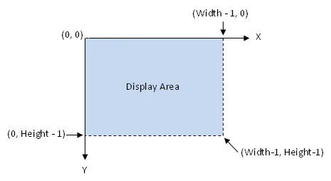
The point selection function provided by the path display allows you to easily select a point on the displayed path and report the selection to a controller. To locate a desired point on the displayed path, use your finger tip to touch the point or move the cursor onto the point. When detecting the release of your finger tip, the path display finds the closest point to the cursor within the search radius and writes the coordinate of the point to the specified work block.
You can complete all the settings of a path display in the Path Display property sheet. This sheet contains the following two pages.
■ General
Described in Section 9.7.3.
■ Visibility
Described in
Section
4.4.6.
In this section
Need PM Designer itself?
V4 for current PK, PT, ITV and PM panels, V2 for older models. Free, sent by email.
Source.Section 9.7 of the PM Designer Software User Manual, Edition 2.0, © Cermate Technologies Inc. (www.cermate.com, service@cermate.com). Reproduced online, with the manual's own figures, by TSL Automation Solutions, authorised Cermate distributor, for users of Cermate HMI panels. PM Designer and PanelMaster are trademarks of Cermate Technologies Inc.
Text and figures are the manufacturer's and may describe features your panel or software version does not have. For a plain-language introduction read the PM Designer guide; for help with a specific panel contact TSL Automation.