Machine Vision System Components: Camera, Lens, Lighting and PC
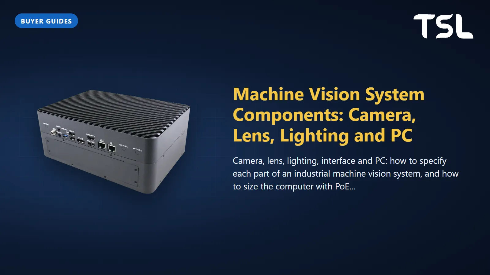
Table of Contents
A machine vision system has five working parts: a camera that turns the part into pixels, a lens that sets the field of view and sharpness, lighting that creates the contrast the software needs, an interface (GigE Vision, USB3 Vision or CoaXPress) that carries images to the computer, and the PC that runs the inspection and tells the PLC to pass or reject. A common mistake is getting one of the first three wrong and then trying to fix it with a bigger computer.
Below, each component in the order you should specify it, then how to size the PC: CPU, NVIDIA Jetson or discrete GPU, with PoE ports and frame grabber slots counted properly.
What is in a machine vision system
From a one-camera label check to a multi-camera surface inspection line, the chain is the same:
- Trigger: a photo sensor or encoder tells the camera when the part is in position.
- Lighting: fires, often strobed, so the feature stands out.
- Lens and camera: form the image and digitise it.
- Interface and cabling: carry the image to the host, often with camera power.
- Vision PC: runs the inspection software (rule-based tools, a trained AI model, or both).
- Output: a signal to the PLC, a reject gate and a traceability record.
Specify physics first, computing last: the computer only sees the contrast and resolution the optics deliver.
The machine vision camera: resolution, sensor and shutter
Start from the smallest feature you must see, not from the megapixel count on a datasheet. A lens fundamentals article in Vision Systems Design gives working benchmarks of about 3 pixels across a feature for detection, 4 for orientation, 10 for recognition and 16 for identification (Vision Systems Design, 2024).
A worked example: you need to detect a 0.2 mm scratch across a 100 mm wide field of view. At 3 pixels per feature, that is 100 / 0.2 x 3 = 1,500 pixels across the field. A sensor about 2,000 pixels wide covers that with margin. To classify the defect rather than just find it, the 10-pixel rule pushes you to 5,000 pixels, or a smaller field of view per camera.
Other camera choices that matter as much as resolution:
- Area scan or line scan: area scan for discrete parts; line scan for continuous material (web, sheet, film) or cylinders rotated past the camera.
- Monochrome or colour: choose colour only when colour is the defect.
- Global or rolling shutter: moving parts need a global shutter, or a strobe short enough to freeze motion.
- Frame rate: parts per second plus headroom.
The lens: focal length, working distance and contrast
The lens decides how much of the part fits on the sensor and how sharp the edges are. The usual first approximation is focal length = (sensor width x working distance) / horizontal field of view (Vision Systems Design).
Example: a sensor 8.8 mm wide, a 300 mm working distance and the 100 mm field of view above gives 8.8 x 300 / 100 = 26.4 mm. Standard lenses come in fixed steps, and because focal length and field of view are inversely related, picking the standard lens one step shorter than the calculated value gives a slightly wider field rather than cutting off the part. Here that is a 25 mm lens.
Two more checks before you order:
- Sensor coverage: the lens image circle must cover the sensor diagonal or the corners vignette.
- Contrast at your resolution: the same article gives 20% contrast as the general minimum for machine vision. A cheap lens on a high-resolution sensor delivers the pixel count without the detail.
Lighting: the component that decides whether it works
Lighting is where most of the inspection is won. Keyence's lighting guide groups it into three methods (Keyence lighting selection):
| Method | How it works | Typical lights | Good for |
|---|---|---|---|
| Specular reflection | The lens receives the direct reflection from the surface | Coaxial, ring, bar | Flat shiny parts, engraved or stamped marks on metal, glass edges |
| Diffuse reflection | The lens receives evenly scattered light | Low-angle, ring, bar, dome | Glare on films and curved shiny parts, chips and texture on dark rubber |
| Transmitted (backlight) | Light from behind; the lens sees a silhouette | Area backlight, bar | Outlines, hole presence, gaps and dimensions |
Colour matters too. The same guide notes that an object lit with its complementary colour appears nearly black, that red light passes through films more easily (useful for reading print under a wrapper), and that infrared can cut surface reflection on some materials. Test lighting on real good and bad parts before freezing the camera and lens; better light often replaces a more complex algorithm.
Camera interfaces: GigE Vision, USB3 Vision and CoaXPress
The interface sets cable length, bandwidth, whether the camera can be powered over its data cable, and what the PC needs on its side. GigE Vision and USB3 Vision both use the GenICam programming interface, so software written for one camera vendor usually carries over to another (A3 GigE Vision, A3 USB3 Vision).
| GigE Vision | USB3 Vision | CoaXPress 2.0 | |
|---|---|---|---|
| Standard body | A3 (AIA) | A3 (AIA) | JIIA |
| Link | Gigabit Ethernet; 10 GigE and link aggregation since v2.0 | USB 3.x, 5 Gbps theoretical on USB 3.0 | Up to 12.5 Gbps per connection (CXP-12); four connections give 50 Gbps |
| Cable length | Up to 100 m on CAT5e/CAT6; fibre also supported | Five metres passive, longer with active cables | 30 m at 12.5 Gbps, 72 m at 6.25 Gbps, over 100 m at 3.125 Gbps |
| Power over the cable | Yes, with Power over Ethernet | Yes, power and data on one cable | Yes, data, control, trigger and power on one coax |
| Host side | Ethernet port per camera or a switch; PoE ports if cameras are powered | USB 3 ports, ideally on separate controllers | PCIe frame grabber |
| Best fit | Most factory cells, long runs, multi-camera | Short runs, compact cells, test benches | High-speed or high-resolution cameras, line scan |
Sources: A3 GigE Vision (v2.0 added 10 GigE in November 2011), A3 USB3 Vision, L-com for USB 3.0 speed, Euresys in Vision Systems Design for CoaXPress 2.0, and the JIIA which hosts CoaXPress.
One recent change: A3's GigE Vision Technical Committee approved GigE Vision 3.0 on 17 April 2026, adding an RDMA (RoCEv2) streaming option for much higher speeds at low CPU load (A3). It matters if you are planning a 10 GigE or faster backbone, less so for a typical small inspection cell.
Sizing the vision PC: CPU, Jetson or discrete GPU
Choose the compute class from the type of software, then fit the camera I/O. Rule-based tools (blob analysis, edge measurement, pattern match, OCR) often run on a modern CPU. Deep-learning defect models need an accelerator: an NVIDIA Jetson module or a discrete GPU. Measure the inference time of your actual model on candidate hardware before you buy; our GPU sizing guide covers the arithmetic.
| Class | When it fits | Example (from the Avalue range we supply) | Camera I/O on the record |
|---|---|---|---|
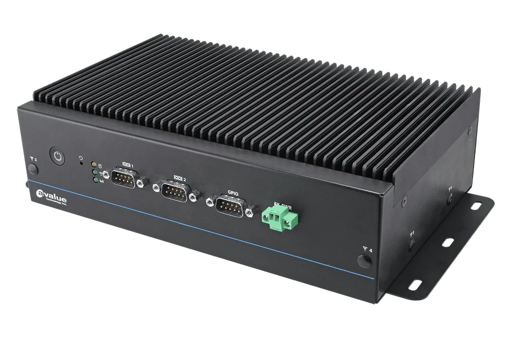
| Fanless x86 box with PoE | Rule-based inspection, barcode and OCR, light AI | EMS-TGL-PSE: 11th Gen Intel Core i7/i5/i3, fanless, -40 to 60°C on the wide-temperature SKU | 4 x IEEE 802.3af PoE ports (60 W total) or 2 x 802.3at, depending on SKU; 9 to 36 V DC input |
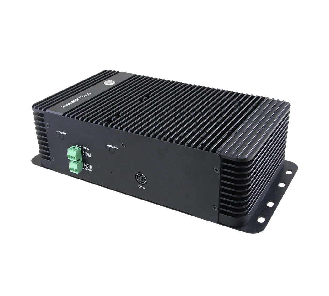
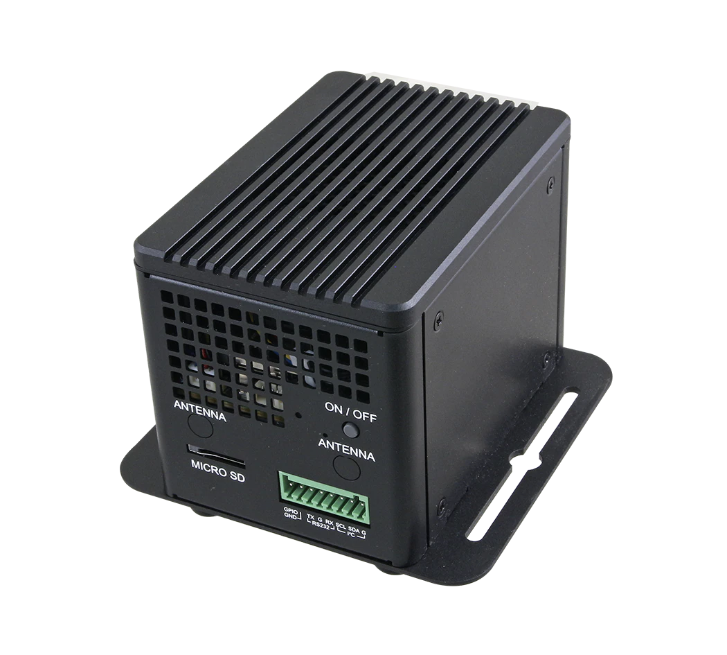
| Entry Jetson | One to a few cameras with a compact AI model | AIB-NW01: Jetson Orin Nano (20/40 TOPS) or Orin NX (70/100 TOPS), -15 to 60°C | 2 x GbE, 4 x USB 3.1 |
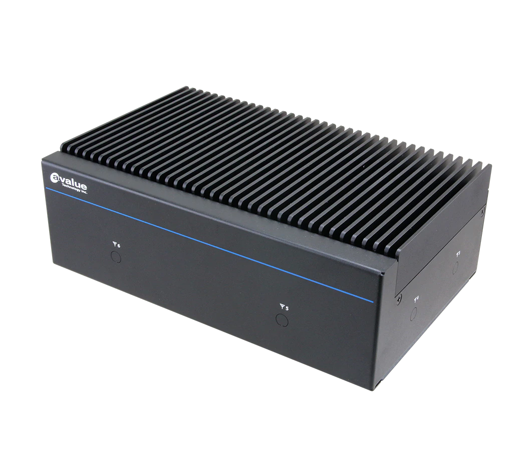
| Mid Jetson | Several cameras, MIPI camera heads | AIB-NINX-S: Jetson Orin NX 8/16 GB, 70/100 TOPS, fanless | 8 internal MIPI CSI-2 lanes, 4 x USB 3.2 Gen2; optional PSE board with 4 x 802.3af ports |
| High Jetson | Many cameras, GMSL2 or SDI capture cards, heavier models | AIB-NIAO-S: Jetson AGX Orin 32/64 GB, 200/275 TOPS | 16 MIPI CSI-2 lanes, 2 x PCIe Gen3 x4 slots for optional capture cards, optional 8 x 802.3af PSE board |
| Discrete GPU workstation | Windows-based AI tools, larger models, one GPU | BMX-P820A (barebone): 14th Gen Core i7, optional NVIDIA RTX A2000 Ada, 300 W ATX PSU, 0 to 40°C | One PCIe x16 slot plus three Gen3 slots wired x1 |
| Multi-GPU server | Centralised inspection for many lines, model retraining | GAI-ERS-Series: Intel Xeon, 4U, 1300 W PSU, 0 to 35°C | 4 x PCIe Gen5 x16 and 3 x Gen5 x4 slots, 2 x 10GbE |
Figures are from the product records on our site.
Counting PoE ports and the power budget
PoE saves a power cable per camera, but check the total budget, not only the port count. Under IEEE 802.3af a port supplies up to 15.4 W, of which 12.95 W is guaranteed at the camera after cable losses; 802.3at (PoE+) raises that to 30 W at the port and 25.5 W at the device (DigiKey). Four 802.3af ports at full load would be 61.6 W at the source, while the EMS-TGL-PSE record lists 60 W total across its PoE ports. Add up the datasheet power of your cameras and any PoE-powered lights, and use a separately powered PoE switch if you are close to the limit.
Frame grabber and NIC slots
CoaXPress cameras need a PCIe frame grabber, and a quad CXP-12 grabber needs a slot with enough electrical lanes to carry its bandwidth. Read the electrical width, not the physical size. On the BMX-P820A only slot 1 is a full x16 link; the other three are x1 electrically, so with a GPU in slot 1 it suits GigE or USB3 cameras rather than a multi-lane grabber. A system with several x16 slots, such as the GAI-ERS-Series, can host a GPU and a grabber together. For GigE Vision, count one Ethernet port per camera (or a switch with enough uplink), and keep the plant network on a separate port.
Environment and lifecycle
Match the operating range to the cabinet. The Jetson systems and the fanless x86 box above are rated up to 60°C with airflow; the GPU workstation and server examples above are rated 0 to 40°C and 0 to 35°C and belong in a cooled enclosure or a server room. Also confirm the operating system support window and spares availability for the life of the line.
A specification checklist
- Smallest feature, field of view, parts per minute and the decision you need (detect, measure, classify, read).
- Pixels required from the 3/4/10/16 rule, then camera resolution and frame rate.
- Working distance, focal length and lens quality at that resolution.
- Lighting method and colour, proven on real good and bad samples.
- Interface from cable length and bandwidth; count PoE watts or frame grabber lanes.
- Compute class from the software and the measured inference time per image.
For the basics of what machine vision does, see What is machine vision; for AI-based defect detection on the line, see computer vision for quality inspection; and for when an NPU or CPU is enough, read NPU vs GPU vs CPU for edge AI. Our machine vision solutions page groups the hardware by application.
How TSL can help
TSL Automation Solutions, based in Mumbai, has been an authorised Avalue and Cermate distributor since 2015 and ships worldwide. For machine vision we supply the computing side: fanless PoE box PCs such as the EMS-TGL-PSE, NVIDIA Jetson AI box PCs (AIB-NW01, AIB-NINX-S, AIB-NINX-SC, AIB-NIAO-S), GPU-ready workstations such as the BMX-P820A, and multi-GPU servers in the GAI-ERS-Series. Try the product finder, or put two candidates side by side in the compare tool. Include your camera count, interface and resolution with the enquiry so the slots, PoE budget and operating range can be checked against the specification sheets.
Send us the model numbers and quantities and we will reply with availability and lead time within one business day.
Frequently Asked Questions
TSL Automation Solutions
Head of Marketing, TSL Automation Solutions
Sanjana covers industrial automation trends, product launches, and technology insights for TSL Automation Solutions, a Mumbai-based distributor of HMI, Panel PC, and embedded computing systems serving manufacturers across India and globally.
Need help choosing the right product?
Our team in Mumbai can recommend the right HMI, Panel PC, or embedded system for your application.
Contact TSL Automation