
Section 13.6.5 · Chapter 13: Data Collection and Historic Displays
Historic Scatter Chart - Pen Settings
This section describes how to define the point selection for the historic scatter chart. The following is an example of the Point Selecction page.
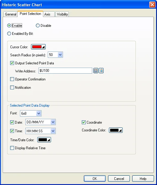
The following table describes each property in the Pen page.
| Property | Description | |||
|---|---|---|---|---|
| Enable | Check this option so the historic scatter chart will display a cursor for point selection. You can touch and drag the cursor to the data point that you want to select. | |||
| Disable | Check this option to disable the point selection. | |||
| Enable By Bit |
Select the option if you want to enable and disable the
point selection capability by a bit. Specify a bit when the option is selected. Click  to enter an address for this field. Click
to select a tag for this field. |
|||
| Cursor Color | The color of the cursor that helps the operator to locate a point. | |||
| Search Radius (in pixels) | The historic scatter chart will find the closest point to the current cursor position within the search circle as the selected point. The center of the search circle is at the current cursor position and the radius is the Search Radius specified here. | |||
| Output Selected Point Data | Check the option to save the selected point data in the specified variable. | |||
| Write Address |
The starting address of a word memory block that will
receive the information of the selected point. Click
to enter an address for this field. Click
 to select a tag for this field. |
|||
| Operator Confirmation | Select the option if the operator confirmation is required before reporting the point selection. | |||
| Notification | <Check Box> | Select the option if notifying a bit is required before reporting the point selection. | ||
| Signal | Select one of the following signals for the notification: | |||
| Signal | Description | |||
| Level | Set the specified bit to the specified state. | |||
| Pulse | Send a positive pulse to the specified bit. | |||
| Bit |
Available when the Notification field is checked.
Specifies the bit for the operation done notification.
Click
to enter an address for this field. Click
to select a tag for this field. |
|||
| State | Specify the state (On or Off) that is used for the notification. | |||
| Selected Point Data Display | Font | Select a font for displaying the values of the selected data point. | ||
| Date |
Check this option to display the date at the top left of
the historic scatter chart object. You need to select a
format for displaying the date. There are 17 formats available: dd/mm/yy, mm/dd/yy, yy/mm/dd, dd.mm.yy, mm.dd.yy, yy.mm.dd, dd-mm-yy, mm-dd-yy, yy-mm-dd, MMMdd, dd/mm, mm/dd, dd.mm, mm.dd, dd-mm, mm-dd, yyyy/mm/dd Note: dd: 01-31 (day); mm: 01-12 (month); yy: 00-99 (year); yyyy: 0000-9999(year); MMM: JAN-DEC (month) |
|||
| Time |
Check this option if you want the object to display the
Time at the top left corner. You need to select a format
for displaying the time. There are 3 formats available:
hh:mm, hh:mm:ss; mm:ss Note: hh: 00-23 (hour); mm: 00-50 (minute); ss: 00-59 (second); |
|||
| Time/Date Color | Select a color to display the Time/Date. | |||
| Display Relative Time | Check this option if you want the object to display a relative measure of time. | |||
| Coordinate | Check this option if you want the object to display the coordinate of the selected point data. | |||
| Coordinate Color | Select a color to display the Coordinate. | |||
Need PM Designer itself?
V4 for current PK, PT, ITV and PM panels, V2 for older models. Free, sent by email.
Source.Section 13.6.5 of the PM Designer Software User Manual, Edition 2.0, © Cermate Technologies Inc. (www.cermate.com, service@cermate.com). Reproduced online, with the manual's own figures, by TSL Automation Solutions, authorised Cermate distributor, for users of Cermate HMI panels. PM Designer and PanelMaster are trademarks of Cermate Technologies Inc.
Text and figures are the manufacturer's and may describe features your panel or software version does not have. For a plain-language introduction read the PM Designer guide; for help with a specific panel contact TSL Automation.