
Section 13.1.2 · Chapter 13: Data Collection and Historic Displays
Data Logger - General Settings
Use the General page to define the general settings for a data logger. The following is an example of the General page.
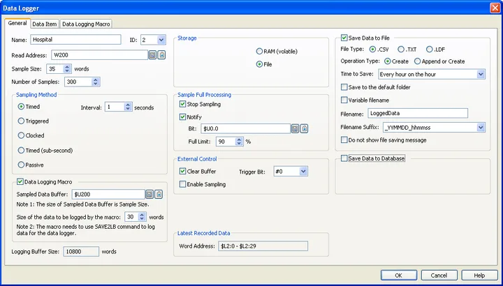
The table below describes each property in the General page.
|
Property |
Description | ||||
|---|---|---|---|---|---|
| Name | The data logger's name. The maximum length of the name is 48 characters. | ||||
| ID | The data logger's ID number. Select a number between 0 and 15. The number is unique among all data loggers of the panel application. | ||||
| Read Address |
Specifies the variable representing the data block to be
sampled. Click  to enter an address for this field. Click  to select a tag for this field. The size of the data block is specified in the Sample Size field. |
||||
| Sample Size | The size of the data to be sampled. The unit is word. | ||||
| Number of Samples | Specifies the maximum number of samples that the logging buffer of the data logger can hold. | ||||
| Sampling Method | Timed | The data logger samples data periodically at a rate specified in the Interval field. You can specify an interval between 1 and 65535 seconds for the Interval field. For example, if you want the data logger to sample data every 5 seconds, specify 5 for the Interval field. | |||
| Triggered | The data logger samples data once whenever the trigger bit specified in the Trigger Bit field changes from Off to On. | ||||
| Clocked | The data logger samples data at fixed moments specified in the At Each field. There are six sets of fixed moments available for the At Each field. | ||||
| At Each | Fixed Moments | ||||
| 1x | Every minute at 0 second | ||||
| 5x | The following moments of every hour: 00:00, 05:00, 10:00, 15:00, 20:00, 25:00, 30:00, 35:00, 40:00, 45:00, 50:00, 55:00 | ||||
| 10x | The following moments of every hour: 00:00, 10:00, 20:00, 30:00, 40:00, 50:00 | ||||
| 15x | The following moments of every hour: 00:00, 15:00, 30:00, 45:00 | ||||
| 30x | The following moments of every hour: 00:00, 30:00 | ||||
| 60x | Every hour on the hour | ||||
| Timed (sub-second) |
The data logger samples data periodically at a rate
specified in the Interval field. You can select an
interval between 0.1 and 0.9 seconds for the Interval
field. For example, if you want the data logger to
sample data every 0.5 seconds, select 0.5 for the
Interval field. The sub-second sampling requires high data acquisition performance. As there are many factors that can affect performance, it is not guaranteed that the specified sampling rate can be attained. |
||||
| Passive | The data logger does not sample data, but receives data from primary data logger by using SAVE2LB macro command or a LDF/CSV/TXT file. For details about the passive method, please see Section 13.1.4. Using File to Save Logged Data. | ||||
| Data Logging Macro | Data Logging Macro | Check the option to log processed data instead of original data. For details about the data logging macro, please see Section 13.1.5. Using Data Logging Macro to log processed data. | |||
| Sampled Data Buffer |
Specifies the variable representing the data buffer for
data logging macro to save the sampled data. The buffer
size is the sample size. Click
to enter an address for this field. Click
to select a tag for this field. |
||||
| Size of the data to be logged by the macro | Specifies the size of the data to be logged by the macro. | ||||
| Logging Buffer Size | The size of the logging buffer. The unit is word. The formula to calculate the size is: | ||||
| Sampling Method | Record Size | Logging Buffer Size | Remark | ||
| Timed (sub-second) | Odd Number | Number of Samples * (Record Size + 6 + 1) |
The number 6 is the size of the time stamp. The number 1 is to make each record double-word aligned. |
||
| Even Number | Number of Samples * (Record Size + 6) | ||||
| All Others | Odd Number | Number of Samples * (Record Size + 5) |
The number 5 is the size of the time stamp. The number 1 is to make each record double-word aligned. |
||
| Even Number | Number of Samples * (Record Size + 5 + 1) | ||||
| Note: If the Data Logging Macro is used, the record size will be the size of the data to be logged by the macro. Otherwise the record size is the sample size. | |||||
| Storage | Battery Backed RAM | Check this option so the logging buffer of the data logger will be located in the battery backed RAM. The logged data will not be lost after power down if the battery backed RAM is used as the logging buffer. | |||
| RAM (volatile) | Check this option so the logging buffer will be located in an ordinary RAM, and the data logger will clear the logging buffer whenever the target panel is powered up. | ||||
| Flash Memory | The X series HMI unit allows the data loggers to save the collected data in the flash memory. This feature enlarges the non-volatile storage for real-time data collection from 1 MB to 100 MB. | ||||
| File | Check this option so the logging buffer will be located in the specified file. | ||||
| Sample Full Processing | Stop Sampling | Check the option if you want the data logger to stop sampling data when the logging buffer is full. | |||
| Notify | Check the option if you want the data logger to set the bit specified in the Bit field to On when the number of collected samples exceeds the limit specified in the Full Limit field. | ||||
| Bit |
Available when the Notify field is checked. Specifies
the bit for the sample full notification. Click
to enter
an address for this field. Click
to select a tag for
this field. |
||||
| Full Limit | Available when the Notify field is checked. Select a percentage as the full limit. When the ratio of collected samples to maximum samples specified in the Number of Samples field exceeds the percentage, the data logger sets the bit specified in the Bit field to On. | ||||
| External Control | Clear Buffer | Check this option so the data logger can be controlled to clear its logging buffer with the trigger bit specified in the Trigger Bit field. | |||
| Trigger Bit | Available when the Clear Buffer option is checked. Select a trigger bit that will control the data logger to clear its logging buffer. The data logger clears its logging buffer when the trigger bit changes from Off to On. | ||||
| Enable Sampling | Check this option so the data logger can be enabled and disabled by the enabling bit specified in the Enabling Bit field. | ||||
| Enabling Bit | Available when the Enable Sampling option is checked. Select an enabling bit that will enable and disable the data logger. The data logger is enabled when the enabling bit is On. | ||||
| Latest Recorded Data | Word Address | You can use the addresses shown here to refer to the latest sampled data of the data logger for configuring screen objects and writing macros. | |||
| Save Data to File | |||||
| Save Data to File | Check this option so the data logger will periodically write the newly collected data to a specified file. Each time the data logger performs this operation, it writes only the data that have not saved to a file before. | ||||
| File Type | The type of file to save the logged data. | ||||
| File Type | Description | ||||
| .CSV/.TXT | The logged data are saved in CSV or text format. You can use any text editor to view the logged data. Most importantly you can use Microsoft Excel to import the logged data from such files directly. | ||||
| .LDF | The logged data are saved in a binary format and can only be used by a data logger that has exactly the same data definition. This file type allows you to view and operate historic data loaded from files. | ||||
| Operation Type | Specifies how to open a file to save the logged data. | ||||
| Operation Type | Description | ||||
| Create | Creates a new file with the specified filename to save the logged data. | ||||
| Append or Create | If the specified file exists, appends the logged data to that file; otherwise creates a new file with the specified filename to save the logged data. | ||||
| Time to Save | Specifies the period to save the logged data. There are fourteen periods available: | ||||
| Available Period | |||||
| Every hour on the hour | |||||
| Every 8 hours (00:00, 08:00, 16:00) | |||||
| Every 12 hours (00:00, 12:00) | |||||
| Every day at 00:00 | |||||
| Every day at 08:00 | |||||
| Every day at 12:00 | |||||
| Every Sunday at 00:00 | |||||
| Every Monday at 00:00 | |||||
| Every month's first day at 00:00 | |||||
| Every Minute (For test only) | |||||
| Every 5 minutes | |||||
| Every 10 minutes | |||||
| Every 15 minutes | |||||
| Every 30 minutes | |||||
| Save to the default folder | Check this option to save the file in the default folder. Please see Section 3.1.4 for details about specifying default folder. | ||||
| Variable filename |
Check this option to use the variable representing the
file name. Click
to enter an address for the
Filename field. Click
to select a tag for the
Filename field. |
||||
| Filename | The filename or the prefix of the filename of the file to save the logged data if the Variable filename option is not checked. The extension name must be "csv" when the File Type is ".CSV". The extension name must be "txt" when the File Type is ".TXT". The extension name must be "ldf" when the File Type is ".LDF". The extension name must be "xls" when the File Type is ".XLS". | ||||
| File name Suffix | Available when the Operation Type is Create and the filename is not a variable. This property guarantees that the created file has a unique name and no existing file will be overwritten. There are four kinds of filename suffixes available as shown in the following table. | ||||
| Filename Suffix | Description | Example | |||
| _YYMMDD_hhmmss |
YY: year (00-99) MM: month (01-12) DD: day (01-31) hh: hour (00-23) mm: minute (00-59) ss: second (00-59) |
Log_090423_102358 (Assume that the specified Filename is "Log", the current date is April 23, 2009, and the current time is 10:23:58.) |
|||
| _YYMMDD_hhmm | Log_090423_1023 | ||||
| _YYMMDD_hh | Log_090423_10 | ||||
| _YYMMDD | Log_090423 | ||||
| Do not show file saving message | Check this option if you do not want to show the message when doing the file saving operation. | ||||
| Save Data to Database | Save Data to Database | Check this option so the data logger will periodically write the newly collected data to a specified table in the database. Each time the data logger performs this operation, it writes only the data that have not saved to a database before. | |||
| Table Name | Specifies the name of the table in the database to save the logged data. | ||||
| Time to Save | Specifies the period to save the logged data. There are fourteen periods available. | ||||
Need PM Designer itself?
V4 for current PK, PT, ITV and PM panels, V2 for older models. Free, sent by email.
Source.Section 13.1.2 of the PM Designer Software User Manual, Edition 2.0, © Cermate Technologies Inc. (www.cermate.com, service@cermate.com). Reproduced online, with the manual's own figures, by TSL Automation Solutions, authorised Cermate distributor, for users of Cermate HMI panels. PM Designer and PanelMaster are trademarks of Cermate Technologies Inc.
Text and figures are the manufacturer's and may describe features your panel or software version does not have. For a plain-language introduction read the PM Designer guide; for help with a specific panel contact TSL Automation.