
Section 13.3.4 · Chapter 13: Data Collection and Historic Displays
Historic Trend Graph - General Settings
This section describes how to define the general settings for a historic trend graph. The following is an example of the General page of the Historic Trend Graph property sheet.
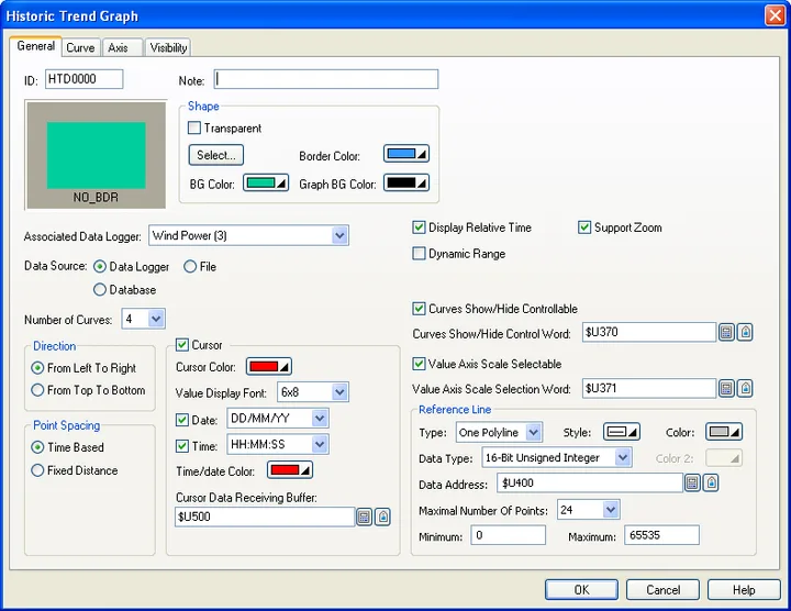
The following table describes each property in the General page.
| Property | Description | |||||||
|---|---|---|---|---|---|---|---|---|
| ID | The object’s identifier. It is generated when the object is created and is unchangeable. The identifier is unique within the screen where the object is located. The format of the IDs for the historic trend graph is HTDnnnn. | |||||||
| Note | You can type a note for the object. | |||||||
| Shape settings |
For details about the following properties, see
Section 4.3.4 Setting up the Shape
of an Object.
 ,
Border Color, BG Color. |
|||||||
| Graph BG color | Select a color for the background of the graph. | |||||||
| Associated Data Logger | Specifies the associated data logger. | |||||||
| Data Source | Select data logger or file as the source of the collected data. | |||||||
| File Buffer ID | Specify the File Buffer ID if the data source is a file. To specify a file buffer ID for a file, you can use Load Logged Data From File operation of the function button. Please see Section 5.4 Performing Built-in Function Using Function Buttons for details. | |||||||
| Number of Curves | Specifies the number of curves. Max 16 curves are supported. | |||||||
| Direction | From Left to Right | Check this option to place the historic trend graph in horizontal direction. | ||||||
| From Top to Bottom | Check this option to place the historic trend graph in vertical direction. | |||||||
| Point Spacing | Time Based | Check this option if you want to draw the distance between two adjacent points based on time. | ||||||
| Fixed Distance | The space between two adjacent data points on a trend curve can be a fixed distance in pixels rather than a distance determined by the time difference of the two points. Check this option if you want to draw the distance between two adjacent points in predefined pixels. You need to specify the distance from the dropdown list with 1,2,4,8,16 or 32 pixels. You can use the fixed distance to draw two adjacent points if the data logger is sampled not by time but by triggered. | |||||||
| Cursor | <Check box> | Check this option so the historic trend graph will display a cursor. You can touch and drag the cursor to the data point(s) that you want to select. | ||||||
| Cursor Color | Select a color for the cursor. | |||||||
| Value Display Font | Select a font for displaying the values of the selected data point(s). | |||||||
| Date |
Check this option to display the date at the top left of
the historic trend graph object. You need to select a
format for displaying the date. There are 17 formats available: dd/mm/yy, mm/dd/yy, yy/mm/dd, dd.mm.yy, mm.dd.yy, yy.mm.dd, dd-mm-yy, mm-dd-yy, yy-mm-dd, MMMdd, dd/mm, mm/dd, dd.mm, mm.dd, dd-mm, mm-dd, yyyy/mm/dd Note: dd: 01-31 (day); mm: 01-12 (month); yy: 00-99 (year); yyyy: 0000-9999(year); MMM: JAN-DEC (month) |
|||||||
| Time |
Check this option if you want the object to display the
Time at the top left corner. You need to select a format
for displaying the time. There are 3 formats available:
hh:mm, hh:mm:ss; mm:ss Note: hh: 00-23 (hour); mm: 00-50 (minute); ss: 00-59 (second); |
|||||||
| Time/Date Color | Select a color to display the Time/Date. | |||||||
| Cursor Data Receiving Buffer |
Specifies the variable to receive the data selected by
the cursor to be read and displayed.
The buffer size is the record size of the associated
data logger.
Click
 to enter an address for this field. Click  to select a tag for this field. |
|||||||
| Display Relative Time | Check this option if you want the object to display a relative measure of time. | |||||||
| Support Zoom | Check this option so the zoom option will be supported at runtime. You may use the function button to zoom in or zoom out of the historic trend graph at the runtime. This field is available only when the Dynamic Range field is not checked. | |||||||
| Dynamic Range | Dynamic Range |
When this option is selected, the following three ranges
can be specified at runtime: * The minimum and the maximum for the Y values of each curve * The maximum time duration for the X axis * The minimum and maximum of the marks for the Y axis The data that specifies the above three ranges should be set and arranged correctly in a memory block called the dynamic range parameter block. You need to specify the dynamic range parameter block in the Dynamic Range Parameter Block field. |
||||||
| Dynamic Range Parameter Block |
Specifies the variable that stores the dynamic range
parameter block for the historic trend graph when
Dynamic Range is selected. Click
to enter an address for this field. Click
to select a tag for this field.The following table shows the data arrangement of the parameter block. |
|||||||
| Word | Description | |||||||
| 0,1 | The maximum time duration for the time axis | |||||||
| 2,3 | The number of major division for the time axis; 32-bit integer number. The minimum value is 1. | |||||||
| 4,5 | The number of sub-division for the time axis; 32-bit integer number. The minimum value is 1. | |||||||
| 6,7 | The minimum of the mark for the value axis. | |||||||
| 8,9 | The maximum of the mark for the value axis. | |||||||
| 10,11 | The minimum of values for curve #1 of the specific scale type. | |||||||
| 12,13 | The maximum of values for curve #1 of the specific scale type. | |||||||
| 14,15 | The minimum of values for curve #2 of the specific scale type. | |||||||
| 16,17 | The maximum of values for curve #2 of the specific scale type. | |||||||
| … | … | |||||||
| 70,71 | The minimum of values for curve #16 of the specific scale type. | |||||||
| 72,73 | The maximum of values for curve #16 of the specific scale type. | |||||||
| Curves Show/Hide Controllable | When this option is selected, you can show or hide a curve by setting or resetting the corresponding bit of the Curves Show/Hide Control Word. | |||||||
| Curves Show/Hide Control Word. |
Specifies the variable that shows or hides the curve when
Curves Show/Hide Controllable is selected. Click
to enter an address for this field. Click
to select a tag for this field. To show #n curve,
please set bit n-1 of the control word to 1. |
|||||||
| Value Axis Scale Selectable | When this option is selected, you can change the value axis scale at runtime by setting Value Axis Scale Selection Word. | |||||||
| Value Axis Scale Selection Word |
Specifies the variable that stores the value axis scale
set when
Value Axis Scale Selectable is selected. Click
to enter an address for this field. Click
to select a tag for this field. You can define up
to 5 sets of scale settings for the value axis of a
historic trend graph. This can be done on the Axis page
of the configuration dialog box. The following
is an example of the multiple scale settings.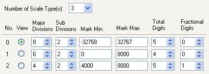 |
|||||||
| Reference Line | Type | The line type and the count of the reference lines. There are three options: One Line, Two Lines, and One Polyline. | ||||||
| Type | Sample | |||||||
| One Line |
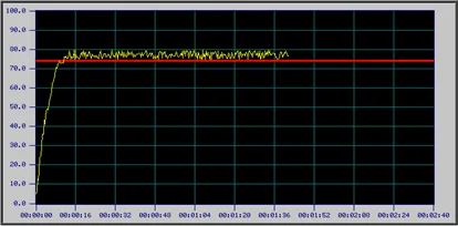 |
|||||||
| One Polyline |
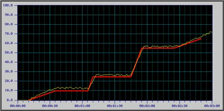 |
|||||||
| Two Lines |
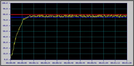 |
|||||||
| Style | Select a line style for the reference lines. | |||||||
| Color | Select a color for the first reference line. | |||||||
| Color 2 | Select a color for the second reference line. It is only available when the type is Two Lines. | |||||||
| Data Type | The data type of the position parameter. The supported data types include:16-Bit Unsigned Integer, 32-Bit Unsigned Integer, 16-Bit Signed Integer, 32-Bit Signed Integer, 16-Bit BCD, 32-Bit BCD, 32-Bit Floating Point. | |||||||
| Data Address |
Specifies the address of the control data. Click
to enter an address for this field. Click
to select a tag for this field. The following
tables describe the arrangements of the control data for
each reference line type. |
|||||||
| Type: One Line | ||||||||
| Word or Double-word No. | Description | |||||||
| 0 | Specifies the line position. (Note 1) | |||||||
| Type: Two Lines | ||||||||
| Word or Double-word No. | Description | |||||||
| 0 | Specifies the position of the first line. (Note 1) | |||||||
| 1 | Specifies the position of the second line. (Note 1) | |||||||
| Type: One Polyline | ||||||||
| Word or Double-word No. | Description | |||||||
| 0 | Specifies how many points the polyline has. The value cannot exceed the specified Maximal Number Of Points. | |||||||
| 1 | Specifies the distance to shift the polyline rightward if the trend graph is of "From Left To Right" or shift the polyline downward if the trend graph is of "From Top To Bottom". The value must be a positive number and the unit is second. | |||||||
| 2 | Specify the time of the first point relative to the time of the trend graph's origin. The unit is second and the value must be a positive number. | |||||||
| 3 | Specify the position of the first point in the direction of the data value axis. (Note 1) | |||||||
| 4 | Specify the time of the second point relative to the time of the trend graph's origin. The unit is second and the value must be greater than the first point's value. | |||||||
| 5 | Specify the position of the second point in the direction of the data value axis. (Note 1) | |||||||
| ... | ... | |||||||
| 2N | Specify the time of the N-th point relative to the time of the trend graph's origin. The unit is second and the value must be greater than the value of the preceding point. | |||||||
| 2N+1 | Specify the position of the N-th point in the direction of the data value axis. (Note 1) | |||||||
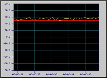
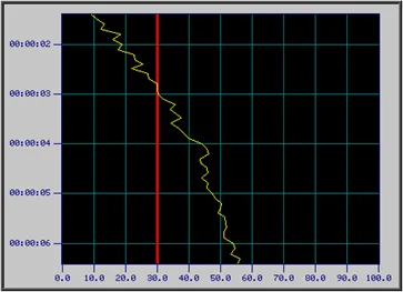
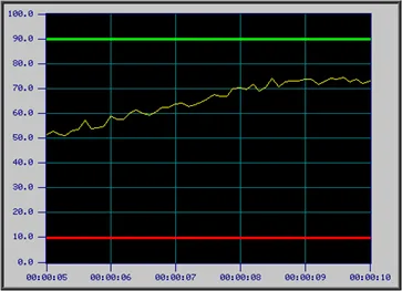
| Note 1: A valid value is between the specified Minimum and Maximum. When the value equals to the Minimum, it positions the associated reference line or the associated point of the reference polyline at the position corresponding to the minimum of the historic data. When the value equals to the Maximum, it positions the associated line or the point at the position corresponding to the maximum of the historic data. When the value is in between, the associated line or point is at a position in the graph area corresponding to the relation of the value among the Minimum and the Maximum. The following are examples with the specified minimum, maximum and control data: | ||||||||
| Minimum | Maximum | Control Data | Example | |||||
| -10 | 10 | 5 |
 |
|||||
| 0 | 100 | 30 |
 |
|||||
| 0 | 100 |
Control Data 1 = 10 Control Data 2 = 90 |
 |
|||||
| 0 | 100 | Word No. | Value | Comment |
|
|||
| 0 | 8 | Number of points | ||||||
| 1 | 0 | No shift | ||||||
| 2 | 10 | Time of the 1st point | ||||||
| 3 | 0 | Value of the 1st point | ||||||
| 4 | 35 | Time of the 2nd point | ||||||
| 5 | 10 | Value of the 2nd point | ||||||
| 6 | 65 | Time of the 3rd point | ||||||
| 7 | 10 | Value of the 3rd point | ||||||
| 8 | 70 | Time of the 4th point | ||||||
| 9 | 25 | Value of the 4th point | ||||||
| 10 | 105 | Time of the 5th point | ||||||
| 11 | 25 | Value of the 5th point | ||||||
| 12 | 115 | Time of the 6th point | ||||||
| 13 | 55 | Value of the 6th point | ||||||
| 14 | 145 | Time of the 7th point | ||||||
| 15 | 55 | Value of the 7th point | ||||||
| 16 | 170 | Time of the 8th point | ||||||
| 17 | 65 | Value of the 8th point | ||||||
| Maximal Number Of Points | The maximal number of points that the reference polyline can have. | |||||||
| Minimum | When the value of the control data equals to the Minimum, it positions the reference lines or the points of the reference polyline at the position corresponds to the minimum of the historic data. | |||||||
| Maximum | When the value of the control data equals to the Maximum, it positions the reference lines or the points of the reference polyline at the position corresponds to the maximum of the historic data. | |||||||
Need PM Designer itself?
V4 for current PK, PT, ITV and PM panels, V2 for older models. Free, sent by email.
Source.Section 13.3.4 of the PM Designer Software User Manual, Edition 2.0, © Cermate Technologies Inc. (www.cermate.com, service@cermate.com). Reproduced online, with the manual's own figures, by TSL Automation Solutions, authorised Cermate distributor, for users of Cermate HMI panels. PM Designer and PanelMaster are trademarks of Cermate Technologies Inc.
Text and figures are the manufacturer's and may describe features your panel or software version does not have. For a plain-language introduction read the PM Designer guide; for help with a specific panel contact TSL Automation.