
Section 20.2.9 · Chapter 20: Setting up Target Panel
VNC Connecting
Part 1: Local network
1. Set IP Address on the HMI
- Find “General” Button in the "Panel Setup" Screen and press it.
- Set “IP Address” to 192.168.10.84, "Subnet Mask" to 255.255.255.0, "Gateway" to 192.168.10.1.
- Press “OK” to save the setting.
2. Connect HMI network cable to a router or a switch.
3. Confirm your new IP address.
Choose an IP address which is not in the range of Starting
and Ending IP Address, for example, 192.168.10.84
On any computer
of the network, move mouse to
“Start -> Programs -> Accessories -> Command Prompt", key in “ping 192.168.10.84”
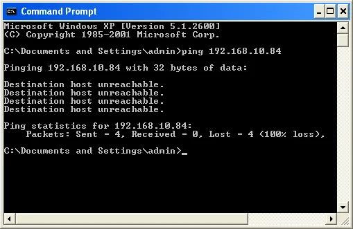
If “Destination host unreachable” appears, this IP address
can be used. Otherwise, choose another IP address and repeat these steps.
4. Start one of VNC Client applications on PC (such as ultraVnc or TightVnc or
realVnc) or on Android or on iPad/iPhone and connect to HMI. Key in HMI's IP address in Server column. Here is
192.168.10.84.
Part 2: Remote network
1. Find a router or a switch, for example:
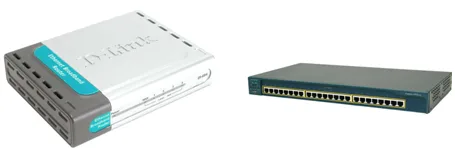
2. Connect a cable from the HMI to this device.
3. Log in the router
Activate your web browser and type in the IP address of the DI-604 into the
Address (for IE) field and press “Enter.” The default IP address of the DI-604
is 192.168.10.1
For example: http://192.168.10.1
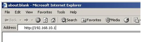
After the connection is established, the logon screen will pop up. To log in as
an administrator, enter the username of “admin” and the password (there are no
default password, leave it blank). Click the OK button. If the password is
correct, the web-management interface will appear.
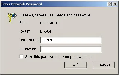
If either User Name or Password is input incorrectly, this dialog will appear
again. Please double check the User Name and Password or ask somebody to get the
correct User Name and Password.
4. Check the starting IP address and the ending IP address.
Move mouse to DHCP button on the left side, and press it.
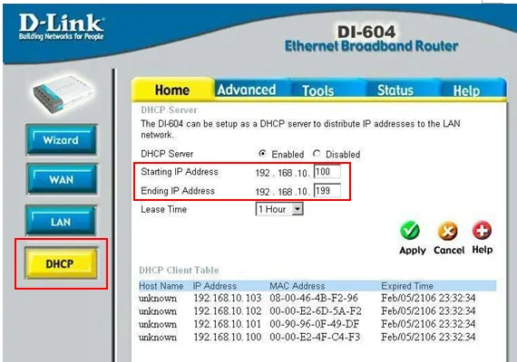
Here are “Starting IP Address” and “Ending IP Address”, They are from
192.168.10.100 to 192.168.10.199.
Choose an IP address which is not in the range of Starting
and Ending IP
Address, for example, 192.168.10.84
5. Set IP Address on the HMI
- Find “General” Button in the "Panel Setup" Screen and press it.
- Set “IP Address” to 192.168.10.84, "Subnet Mask" to 255.255.255.0, "Gateway" to 192.168.10.1.
- Press “OK” to save the setting.
6. Confirm your new IP address.
On any computer of the network, move mouse to
“Start -> Programs -> Accessories -> Command Prompt, key in “ping 192.168.10.84”
If “Destination host unreachable” appears, this IP address can be used.
Otherwise, choose another IP address and repeat these steps.
7. Again, go back to router set page. Press “Advanced” Button on the top row and
press “Virtual Server” on the left column.
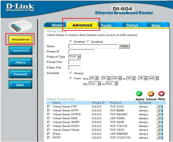
The DI-604 can be configured as a virtual server so that remote users accessing
Web or FTP services via the public IP address can be automatically redirected to
local servers in the LAN network.
The following table describes each property of the Virtual Server.
|
Property |
Description | Remark |
|---|---|---|
| Name | The name referencing the virtual service. | |
| Private IP | The server computer in the LAN network that will be providing the virtual services. | |
| Private Port | The port number of the service used by the Private IP computer. | |
| Protocol Type | The protocol used for the virtual service. | |
| Public Port | The port number on the WAN side that will be used to access the virtual service. | |
| Schedule | The schedule of time when the virtual service will be enabled. | The schedule may be set to Always, which will allow the particular service to always be enabled. If it is set to Time, select the time frame for the service to be enabled. If the system time is outside of the scheduled time, the service will be disabled. |
After finishing set, press ”Apply” button on the bottom to save the new settings. The following is the sample setting:
Name: VNC Server
Private IP: 192.168.10.84
Protocol Type: TCP
Private Port: 5900
Public Port:
5900
Schedule: always
8. Get the external IP Address.
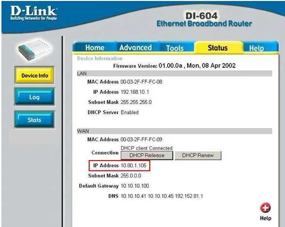
This is the router’s working status. Pay attention to WAN area. Write
down the IP Address. This is an Internet address which every one can visit it.
In this example, it is 10.80.1.105.
9. Test this IP Address.
Run HMI unit. Go to Panel
-> Send Data to Panel -> Ethernet -> IP address. Enter the
IP address which you got from router’s status. The example is 10.80.1.105. And
press the “Start” button to start downloading.
10. Release this IP address to any one who wants to use remote downloading
function.
Basically, this is a dynamic IP address. It is going to keep same in a few days,
even a few months. But it will be changed at any time. So please check it every
time when download is needed.
11. Start one of VNC Client applications on PC (such as ultraVnc or TightVnc or
realVnc) or on Android or on iPad/iPhone and connect to HMI. Key in HMI's external IP address which is from
step 8.
Need PM Designer itself?
V4 for current PK, PT, ITV and PM panels, V2 for older models. Free, sent by email.
Source.Section 20.2.9 of the PM Designer Software User Manual, Edition 2.0, © Cermate Technologies Inc. (www.cermate.com, service@cermate.com). Reproduced online, with the manual's own figures, by TSL Automation Solutions, authorised Cermate distributor, for users of Cermate HMI panels. PM Designer and PanelMaster are trademarks of Cermate Technologies Inc.
Text and figures are the manufacturer's and may describe features your panel or software version does not have. For a plain-language introduction read the PM Designer guide; for help with a specific panel contact TSL Automation.