
Section 8.6.3 · Chapter 8: Graphs and Charts
Rotation Indicator - General Settings
This section describes how to define the general settings for rotation indicators. The following is an example of the General page of the Rotation Indicator property sheet.
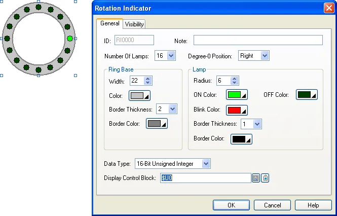
The following table describes each property in the General page.
|
Property |
Description | ||||
|---|---|---|---|---|---|
| ID | The object’s identifier. It is generated when the object is created. The identifier is unique within the screen where the object is located. The format of the IDs for rotation indicators is RInnnn. | ||||
| Note | You can type a note for the object. | ||||
| Number of Lamps | Specifies how many lamps the object has. The maximum is 40. | ||||
| Degree-0 Position | Select the position you want the degree-0 lamp located. The position can be on the left or the right or the top or the bottom. | ||||
| Ring Base | Width | The thickness of the ring in pixel. | |||
| Color | The color of the ring. | ||||
| Border Thickness | The thickness of the ring border in pixel. Select 0 if no border is desired. | ||||
| Border Color | The color of the ring border. | ||||
| Lamp | Radius | The radius of the lamps in pixel. | |||
| ON Color | The color of the lamps when they are turned on. | ||||
| OFF Color | The color of the lamps when they are turned off. | ||||
| Blink Color | The color of the lamps when they are turned on while blinking. | ||||
| Border Thickness | The thickness of the lamps’ border in pixel. Select 0 if no border is desired. | ||||
| Border Color | The Color of the lamps' border. | ||||
| Data Type | The type of the data that controls the object. | ||||
| Display Control Block |
Specifies the address or tag of the display control
block that controls the object. The display control
block can be an unsigned word array or an unsigned
double-word array with 3 data members.
The following table shows the data members of the display control block. |
||||
| Word No. or Double-word No. | Data Member | Description | |||
| 0 | Command Word | Stores the command code of the desired operation. | |||
| 1 | Speed Control Word | Specifies the speed for the animated rotation or the lamp blinking operation. | |||
| 2 | Angle Control Word | Stores the angle to be indicated by the object. | |||
|
The following table describes the operation of each command code. |
|||||
| Command Code | Description | ||||
| 0 | Turns off all lamps | ||||
| 1 |
Indicates the angle specified in the Angle Control Word,
The angle is counted clockwise as shown below.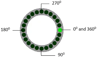 Angle Control Word |
||||
| Value | Description | ||||
| 0-360 | Valid angles | ||||
| Others | Invalid angles. The values are ignored. | ||||
| 2 |
Indicates the angle specified in the Angle Control Word.
The angle is counted counter-clockwise as shown below.
See the description of Angle Control Word in the above
cell.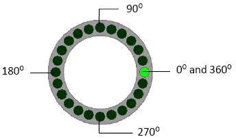 |
||||
| 3 |
Shows the animated clockwise rotation with the speed
specified in the Speed Control Word.
Speed Control Word |
||||
| Value | Description | ||||
| 0 | Invalid number. Value 1 is assumed. | ||||
| 1-1000 | The interval that a lamp takes turns to light. The unit is 0.01 second. If the object has N lamps and the value in the Speed Control Word is V, the time of one rotation is N x V x 0.01 second. For example, if the object has 20 lamps and the value is 5, the time of one rotation is 20 x 5 x 0.01 = 1 second. Note tha thte system may not be able to perform as fast as the specified. | ||||
| Others | Invalid numbers. Value 1000 is assumed. | ||||
| 4 | Shows the animated counter-clockwise rotation with the speed specified in the Speed Control Word. See the description of Speed Control Word in the above cell | ||||
| 5 | Turns on the lamp of degree-zero only. | ||||
| 6 | Turns on all the lamps. | ||||
| 7 |
Blinks all the lamps together at the
speed specified in the Speed Control Word.
Speed Control Word |
||||
| Value | Description | ||||
| 0 | Invalid number. The value 1 is assumed. | ||||
| 1-100 | The interval to blink the lamps once. The unit is 0.1 second. For example, the value of 10 will cause the lamps to blink once every second. Note that the system may not be able to perform as fast as the specified. | ||||
| Others | Invalid numbers. The value 100 is assumed. | ||||
|
Click  to bring up the Address Input Keypad and specify the
desired address for the Display Control Block field. Click  to bring up the Select Tag dialog box and select the
desired tag for the Write Display Control Block field. |
|||||
Need PM Designer itself?
V4 for current PK, PT, ITV and PM panels, V2 for older models. Free, sent by email.
Source.Section 8.6.3 of the PM Designer Software User Manual, Edition 2.0, © Cermate Technologies Inc. (www.cermate.com, service@cermate.com). Reproduced online, with the manual's own figures, by TSL Automation Solutions, authorised Cermate distributor, for users of Cermate HMI panels. PM Designer and PanelMaster are trademarks of Cermate Technologies Inc.
Text and figures are the manufacturer's and may describe features your panel or software version does not have. For a plain-language introduction read the PM Designer guide; for help with a specific panel contact TSL Automation.