
Section 8.2.4 · Chapter 8: Graphs and Charts
Meter - General Settings
This section describes how to define the general settings for a meter.
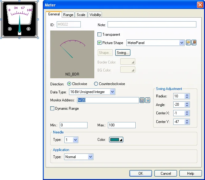
The above is an example of the General page of the Meter property sheet.
The following table describes each property in the General page.
|
Property |
Description | ||
|---|---|---|---|
| ID | The object’s identifier. It is generated when the object is created. The identifier is unique within the screen where the object is located. The format of the IDs for the meters is Mnnnn. | ||
| Note | You can type a note for the object. | ||
| Transparent | Select this option if you want the object to have a transparent background. | ||
| Picture Shape | Picture Shape |
Check this option if you want to use a picture for the
meter’s shape. You can use a picture to customize your
own meter. For example: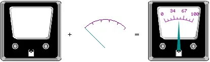 Note: If Picture Shape is checked, Shape…, Border Color and BG Color fields are not available to be used. |
|
| <Drop-down List> | The name of the picture. You can use the drop-down list to select a picture from the picture database. | ||
 |
Click this icon to select a picture file. After selection, the picture of the selected file is imported and saved in the picture database. | ||
 |
Click this icon to bring up the Select/Import from Library dialog box. Select a picture from a picture library file. After selection, the selected picture is imported and saved in the picture database. | ||
| Graphical shape settings |
For details about the following properties,
Section 4.3.4 Setting up the
Shape of an Object.
 ,
Border Color, BG Color |
||
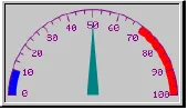
| Swing |
Specifies the type of swing. For details,
see Section 8.2.1 Basic Operation. The swing styles below are more space saving because their needles can be placed outside the shape by changing the position of Center X or Center Y. 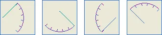 |
||
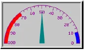
| Direction | Specifies the direction that the needle moves either clockwise or counter clockwise. | ||
| Counter clockwise | Clockwise | ||
 |
 |
||
| Data Type | The data type of the monitored variable. The supported data types include: 16-Bit Unsigned Integer, 32-Bit Unsigned Integer, 16-Bit Signed Integer, 32-Bit Signed Integer, 16-Bit BCD, 32-Bit BCD, 32-Bit Floating Point, 16-Bit Signed BCD (LMB), 32-Bit Signed BCD (LMB), 16-Bit Signed BCD (LMD), and 32-Bit Signed BCD (LMD). | ||
| Monitor Address |
Specifies the variable to be monitored. Click  to enter an address for this field. Click  to select a tag for this field. If the application type is Tower Crane, the variable stores parameter block to displaying the tower crane. The following table shows the content of the parameter block when the data type is 16-bit : |
||
| Word | Parameter | ||
| 0 | The jib position in degree. The valid number is between 0 and 360. | ||
| 1 | The distance in pixel between the lifting hook position and the center. | ||
| 2 | The jib length in pixel which is the distance between the end of the jib and the center. | ||
| 3 | The counterjib length in pixel which is the distance between the end of the counterjib and the center. | ||
| 4 | The X position of the center (tower crane) which is relative to the upper-left corner of the panel. | ||
| 5 | The Y position of the center (tower crane) which is relative to the upper-left corner of the panel. | ||
| 6 | The X position of the upper-left corner of the viewable area. | ||
| 7 | The Y position of the upper-left corner of the viewable area. | ||
| 8 | The X position of the lower-right corner of the viewable area. | ||
| 9 | The Y position of the lower-right corner of the viewable area. | ||
|
The following table shows the content of the parameter block when the data type is 32-bit |
|||
| Word | Parameter | ||
| 0,1 | The jib position in degree. The valid number is between 0 and 360. | ||
| 2,3 | The distance in pixel between the lifting hook position and the center. | ||
| 4,5 | The jib length in pixel which is the distance between the end of the jib and the center. | ||
| 6,7 | The counterjib length in pixel which is the distance between the end of the counterjib and the center. | ||
| 8,9 | The X position of the center (tower crane) which is relative to the upper-left corner of the panel. | ||
| 10,11 | The Y position of the center (tower crane) which is relative to the upper-left corner of the panel. | ||
| 12,13 | The X position of the upper-left corner of the viewable area. | ||
| 14,15 | The Y position of the upper-left corner of the viewable area. | ||
| 16,17 | The X position of the lower-right corner of the viewable area. | ||
| 18,19 | The Y position of the lower-right corner of the viewable area. | ||
| Note: The part of the tower crane that is outside of the viewable area will not be drawn/shown. | |||
| Dynamic Range | Dynamic Range | Check this option so the minimum and maximum of the monitored variable will be specified at runtime. When this option is selected, the minimum and maximum of the marks for the scale of the meter can be specified at runtime as well. The data that specifies the above two ranges should be set and arranged correctly in a memory block called the dynamic range parameter block. You need to specify the dynamic range parameter block for the meter in the Dynamic Range Parameter Block field. | |
| Dynamic Range Parameter Block |
Specifies the variable that stores the dynamic range
parameter block for the meter when Dynamic Range is
selected. Click
to enter an address for this field.
Click
to select a tag for this field. The following table shows the content of the parameter block when the data type is 16-bit and the scale of the meter is not dynamic. |
||
| Word | Parameter | ||
| 0 | The minimum of the monitored variable | ||
| 1 | The maximum of the monitored variable | ||
| The following table shows the content of the parameter block when the data type is 16-bit and the scale of the meter is dynamic. | |||
| Word | Parameter | ||
| 0 | The minimum of the monitored variable | ||
| 1 | The maximum of the monitored variable | ||
| 2, 3 | The minimum of the mark for the scale; 32-bit integer number | ||
| 4, 5 | The maximum of the mark for the scale; 32-bit integer number | ||
| The following table shows the content of the parameter block when the data type is 32-bit and the scale of the meter is not dynamic. | |||
| Word | Parameter | ||
| 0, 1 | The minimum of the monitored variable | ||
| 2, 3 | The maximum of the monitored variable | ||
| The following table shows the content of the parameter block when the data type is 32-bit and the scale of the meter is dynamic. | |||
| Word | Parameter | ||
| 0, 1 | The minimum of the monitored variable | ||
| 2, 3 | The maximum of the monitored variable | ||
| 4, 5 | The minimum of the mark for the scale; 32-bit integer number | ||
| 6, 7 | The maximum of the mark for the scale; 32-bit integer number | ||
| Min. |
Specifies the minimum value of the monitored variable when
Dynamic Range is not selected.
Note that the data range of meters can be beyond -1000000 and 1000000. |
||
| Max. |
Specifies the maximum value of the monitored variable when
Dynamic Range is not selected. Note that the data range of meters can be beyond -1000000 and 1000000. |
||
| Swing Adjustment | Radius | You can adjust the radius of the swing of the needle. This field specifies the offset to be added to the default radius. | |
| Angle | You can adjust the span of the swing of the needle. This field specifies the offset to be added to the default span. | ||
| Center X | You can adjust the horizontal position for the pivot of the needle. This field specifies the offset to be added to the default horizontal position. | ||
| Center Y | You can adjust the vertical position for the pivot of the needle. This field specifies the offset to be added to the default vertical position. | ||
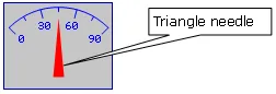
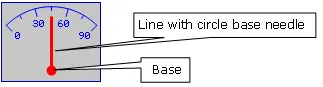
| Needle | Type | Select a type for the needle. There are two types: | |
| Type | Description | ||
| 1 |
 |
||
| 2 |
 |
||
| Color | Select a color for the needle. The appearance of meters' needle is improved by the anti-aliasing graphic functions. | ||
| Base Size | Select the radius in pixel of the circle base when the needle type is 2. | ||
| Application | Type | Select a meter type for the application. | |
| Type | Description | ||
| Normal | For normal purpose, it shows the value of a monitored variable by rotating its needle to the appropriate place. | ||
| Tower Crane | For tower cranes, it shows how the jib rotates and the position of the lifting hook. For details, see Section 8.2.6. Anti-collision system for tower cranes. | ||
| Center Color | Select a color for the center. Available only when the application type is Tower Crane. | ||
| Lifting Hook Position Color | Select a color for the hook position. Available only when the application type is Tower Crane. | ||
Need PM Designer itself?
V4 for current PK, PT, ITV and PM panels, V2 for older models. Free, sent by email.
Source.Section 8.2.4 of the PM Designer Software User Manual, Edition 2.0, © Cermate Technologies Inc. (www.cermate.com, service@cermate.com). Reproduced online, with the manual's own figures, by TSL Automation Solutions, authorised Cermate distributor, for users of Cermate HMI panels. PM Designer and PanelMaster are trademarks of Cermate Technologies Inc.
Text and figures are the manufacturer's and may describe features your panel or software version does not have. For a plain-language introduction read the PM Designer guide; for help with a specific panel contact TSL Automation.