
Section 8.6 · Chapter 8: Graphs and Charts
Rotation Indicators
A rotation indicator can display the status of a rotation device. It has a multiple of 4 lamps distributed evenly on its ring base as shown in the following figure. By controlling the lamps' on and off, it generates intuitively understandable messages for showing the status of the associated device.
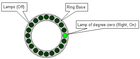
You can command the object to do the following:
1) Turn off all the lamps to indicate that the device is off or inactive.
2) Turn on only the lamp that is the closest one to the specified angle to indicate the angular position of the device.
3) Make the lamps take turns to light in the specified sequence to generate the visual effect of rotation.
4) Turn on only the lamp of degree-zero to indicate that the device is ready or at its initial position.
5) Turn on all the lamps to indicate that the device is shut down or under initialization.
6) Blink all the lamps together with the specified speed to indicate that the device has an urgent condition.
7) Specify the degree-zero position on the left/right/top/bottom.
To create a rotation indicator, select the menu item "Object>>Graph/Chart>> Range Indicator" and place the new object on the current screen.
You can complete all the settings of a rotation indicator in the Rotation Indicator property sheet. This sheet contains the following two pages.
■ General
Described in Section 8.6.3.
■ Visibility
Described in
Section 4.4.6.
In this section
Need PM Designer itself?
V4 for current PK, PT, ITV and PM panels, V2 for older models. Free, sent by email.
Source.Section 8.6 of the PM Designer Software User Manual, Edition 2.0, © Cermate Technologies Inc. (www.cermate.com, service@cermate.com). Reproduced online, with the manual's own figures, by TSL Automation Solutions, authorised Cermate distributor, for users of Cermate HMI panels. PM Designer and PanelMaster are trademarks of Cermate Technologies Inc.
Text and figures are the manufacturer's and may describe features your panel or software version does not have. For a plain-language introduction read the PM Designer guide; for help with a specific panel contact TSL Automation.