
Section 8.5.1 · Chapter 8: Graphs and Charts
Scatter Chart - Basic Operations
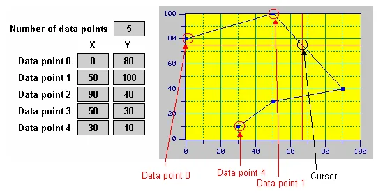
A scatter chart displays a set of data by drawing a data point for each datum and drawing a line that connects all the data points in sequence. Each datum is a coordinate that contains an X value and a Y value. The vertical position of a data point is determined by the X value of the associated datum. The horizontal position of a data point is determined by the Y value of the associated datum.
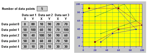
A scatter chart can display up to 8 sets of data. The following example shows a scatter chart that displays 3 sets of data.
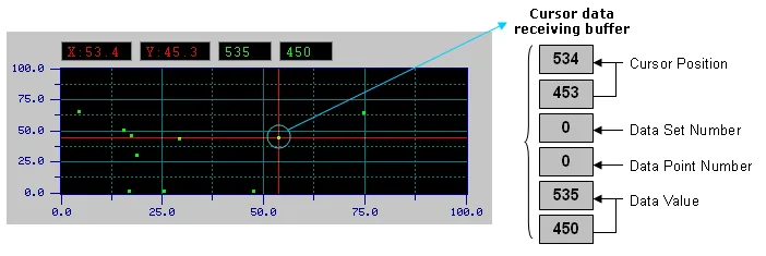
A scatter chart can provide a cursor for you to select desired data points. The cursor of the scatter chart is a cross. The user can move and snap the cursor vertically and horizontally within a scatter chart to the nearest data point. The value of the selected data point can be displayed and output to an internal variable called Cursor Data Receiving Buffer.
You can complete all the settings of a scatter chart in the Scatter Chart dialog box. This dialog box contains the following four pages.
■ General
Described in Section 8.5.4.
■ Pen
Described in
Section
8.5.5.
■ XY Axis
Described in
Section
8.4.6.
■ Visibility
Described in
Section
4.4.6.
Need PM Designer itself?
V4 for current PK, PT, ITV and PM panels, V2 for older models. Free, sent by email.
Source.Section 8.5.1 of the PM Designer Software User Manual, Edition 2.0, © Cermate Technologies Inc. (www.cermate.com, service@cermate.com). Reproduced online, with the manual's own figures, by TSL Automation Solutions, authorised Cermate distributor, for users of Cermate HMI panels. PM Designer and PanelMaster are trademarks of Cermate Technologies Inc.
Text and figures are the manufacturer's and may describe features your panel or software version does not have. For a plain-language introduction read the PM Designer guide; for help with a specific panel contact TSL Automation.