
Section 4.1.3 · Chapter 4: Designing Screens
Drawing Polylines
- In the Draw menu or Draw toolbar, click Polyline
 to draw a polyline.
- Move the cursor onto the screen where you want to draw a polyline, and click the position where you want the start point of the polyline to be at.
- Continue clicking on the screen to place as many points needed for nodes in the polyline.
- Right-click to place the last point for the polyline and complete the polyline.
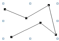
- Drag one blue handle of the polyline at a time to resize the polyline.
- Drag one black handle of the polyline at a time to adjust the node positions of the polyline.
|
The picture on the left shows all the blue and black
handles of a polyline. Position the mouse pointer over one of the
handles. When the cursor changes to
 or  or  or  , drag the handle
until the polyline is the shape and size you want. |
-
Right-click anywhere on the polyline and use the Insert Point command on the object pop-up menu to insert a new point for the polyline. Or right-click the existing point of the polyline and use the Delete Point command on the object pop-up menu to delete the point.
|
Pop-up menu |
Description |
|---|---|
| Insert Point |
Add a point at the specified position.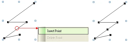 |
| Delete Point |
Delete a selected point.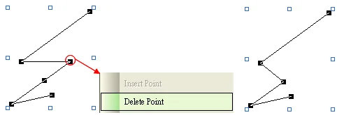 |
- Double-click the polyline to bring up the Polyline dialog box and then
modify the settings of the polyline.
The following is a sample of the Polyline dialog box.
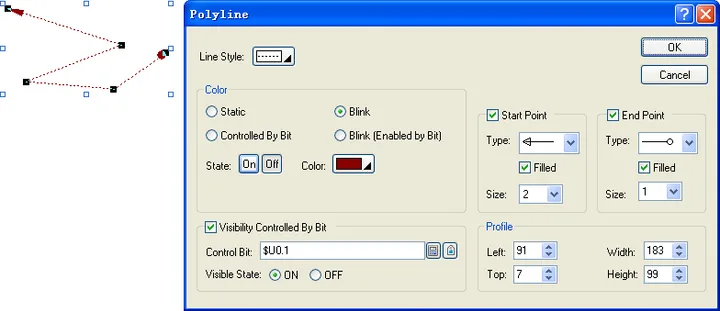
The following table describes each property in the Polyline dialog box.
|
Property |
Description | |||
|---|---|---|---|---|
| Line Style |
Specifies the style of the polyline. |
|||
| Color | Static | Check this option if the color of the polyline will not be changed. | ||
| Controlled By Bit | Check this option if the color of the polyline will be controlled by the specified bit. | |||
| Blink | Check this option so the polyline will blink. You have to choose the blink effects that change the color of the polyline from its On state color to Off state color. | |||
| Blink (Enabled by Bit) | Check this option if you want to enable the polyline blinking by the specified bit. | |||
| State | Select the state that you want to view or define the color for. | |||
| Color | Specifies the polyline color for the selected state. | |||
| Control Bit |
Specifies the bit or the word's bit that controls the color or enables the
color blinking. Click  to enter the bit address. Click  to enter the bit tag. |
|||
| Start Point | Start Point | Select this option if you want the polyline to have a shape at the start point. | ||
| Type | Specifies the shape type. | |||
| Filled | Select this option if you want the shape to be filled with the line color. | |||
| Size | Specifies the shape size. | |||
| End Point | End Point | Select this option if you want the polyline to have a shape at the end point. | ||
| Type | Specifies the shape type. | |||
| Filled | Select this option if you want the shape to be filled with the line color. | |||
| Size | Specifies the shape size. | |||
| Visibility Control | Visibility Controlled By Bit | Check this option if the line will be shown or hidden by the specified bit. | ||
| Control Bit |
Specifies the bit that shows or hides the object.
Click
to enter the bit address. Click
to enter the bit tag. |
|||
| Visible State | Specifies the state (On or Off) that makes the line visible. | |||
| Profile | Left | The X coordinate of the upper-left corner of the bounding rectangle of the polyline. | ||
| Top | The Y coordinate of the upper-left corner of the bounding rectangle of the polyline. | |||
| Width | The width of the bounding rectangle of the polyline. | |||
| Height | The height of the bounding rectangle of the polyline. | |||
You can click the following icons in the Draw toolbar to modify the properties of the polyline.
|
Click Icon |
To |
|---|---|
 |
Select a style for the polyline. |
 |
Select a color for the polyline. |
Need PM Designer itself?
V4 for current PK, PT, ITV and PM panels, V2 for older models. Free, sent by email.
Source.Section 4.1.3 of the PM Designer Software User Manual, Edition 2.0, © Cermate Technologies Inc. (www.cermate.com, service@cermate.com). Reproduced online, with the manual's own figures, by TSL Automation Solutions, authorised Cermate distributor, for users of Cermate HMI panels. PM Designer and PanelMaster are trademarks of Cermate Technologies Inc.
Text and figures are the manufacturer's and may describe features your panel or software version does not have. For a plain-language introduction read the PM Designer guide; for help with a specific panel contact TSL Automation.