
Section 3.1.5 · Chapter 3: Creating Panel Applications
Avoiding Data Corruption Due To Random Power-off
The HMI unit stores various kinds of data in non-volatile storage devices. The data include data log, alarm log, operation log, recipes, schedules, non-volatile user data, and so on. The storage devices include built-in battery backed RAM, built-in flash disk, Micro SD card, and USB memory stick. Turning off the HMI unit while it is writing data to a storage device could fail the write operation. This results in data loss, ruined data integrity, and troublesome sectors in the storage device. In order to avoid the problem, the function button supports a new operation named "Stop Operation Safely". The operator can activate such a function button to stop the HMI operation before turning the power off and it guarantees that all operations with the non-volatile storage devices are safely completed. Although the chance of data corruption is rare, we still recommend you to use the method described here to make your product/project more reliable.
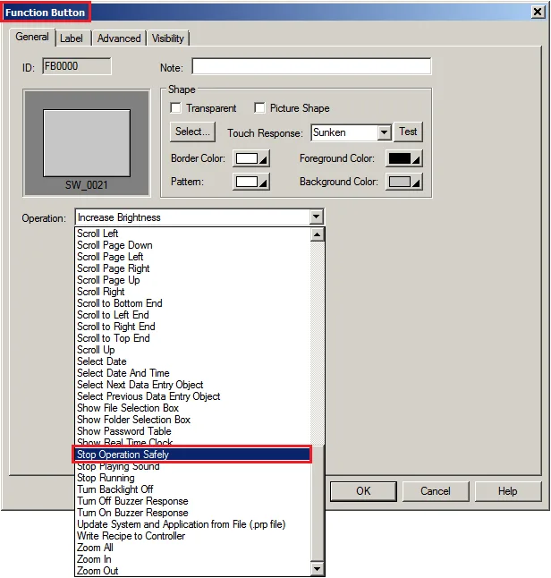
1. The following figure shows how to select the "Stop Operation Safely" operation for a function button.
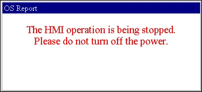
2. The HMI unit will display the following message when you press a "Stop Operation Safely" function button.
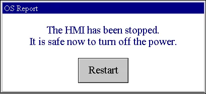
3. The HMI unit will display the following message when it stops the current application successfully.
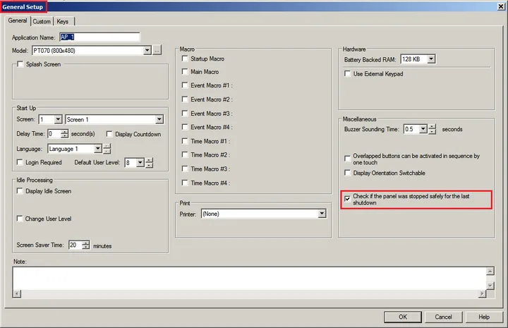
4. You can configure the HMI unit to check if the operator performed the safe stop successfully for the last power-off. The check occurs when the HMI starts running the application every time. The following figure shows how to enable the check of safe stop.
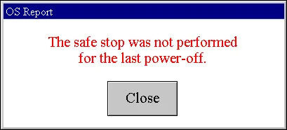
5. The HMI unit will display the following message when it detects that the operator did not perform the safe stop successfully for the last power-off.
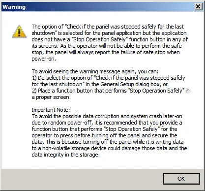
6. The software will display the following warning message when compiling a panel application if the application requires the check of safe stop but the software found no "Stop Operation Safely" function button in any of the application's screens.
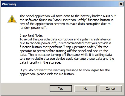
7. The software will display the following warning message when compiling a panel application if the application will save data to battery backed RAM but the software found no "Stop Operation Safely" function button in any of the application's screens. If you do not want to see the message again for the current application, click the No button in the message box. Note that the message will only display for the applications that were created with V2.0.4.11 or later.
Need PM Designer itself?
V4 for current PK, PT, ITV and PM panels, V2 for older models. Free, sent by email.
Source.Section 3.1.5 of the PM Designer Software User Manual, Edition 2.0, © Cermate Technologies Inc. (www.cermate.com, service@cermate.com). Reproduced online, with the manual's own figures, by TSL Automation Solutions, authorised Cermate distributor, for users of Cermate HMI panels. PM Designer and PanelMaster are trademarks of Cermate Technologies Inc.
Text and figures are the manufacturer's and may describe features your panel or software version does not have. For a plain-language introduction read the PM Designer guide; for help with a specific panel contact TSL Automation.