
Section 3.4.12 · Chapter 3: Creating Panel Applications
Using the OPC UA Client Driver
The configuration program provides a built-in OPC UA Client that enables connections to OPC Servers. The NEO OPC Client is built with the OPC Client SDK and can be used to interactively browse and retrieve a Server's Address Space. After the Server's Address Space (or part of the Address Space) being imported to the configuration program, the object instances in the Address Space can be selected as tags.
■ NEO OPC Client Driver
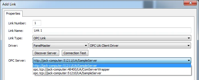
The NEO OPC Client can be launched by configuring an OPC Link from the New Link or Add Link dialog as the followings:
1) From the Link Type combo-box, select OPC Link.
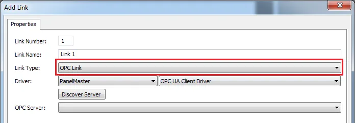
2) From the Driver combo-box, select OPC UA Client Driver.
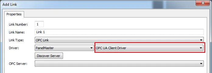
3) The built-in OPC Client can discover any registered OPC Servers running on the local machine after the Discover Server button is clicked. A list of registered OPC Servers will be displayed after this button is clicked.
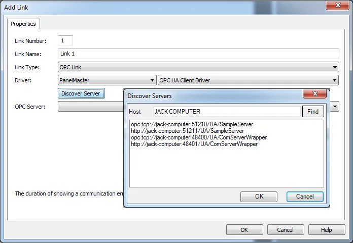
To discover any OPC Servers running on other network hosts, type the host's correct URL or computer name of the target machine into the Host field, and then press the Find button to find all registered OPC Servers running on the specified remote host.
4)
After selecting a target OPC Server, press the Connection Test
button to create a new session to the OPC Server if it is running. If user
authentication is required by the OPC Server, a user name and password are
necessary. The authentication modes depend on the endpoint of the Server. Only
options available for the current endpoint will be displayed. The user
name/password may be left blank. If a user name is specified then it must be a
valid windows account on the Server machine. 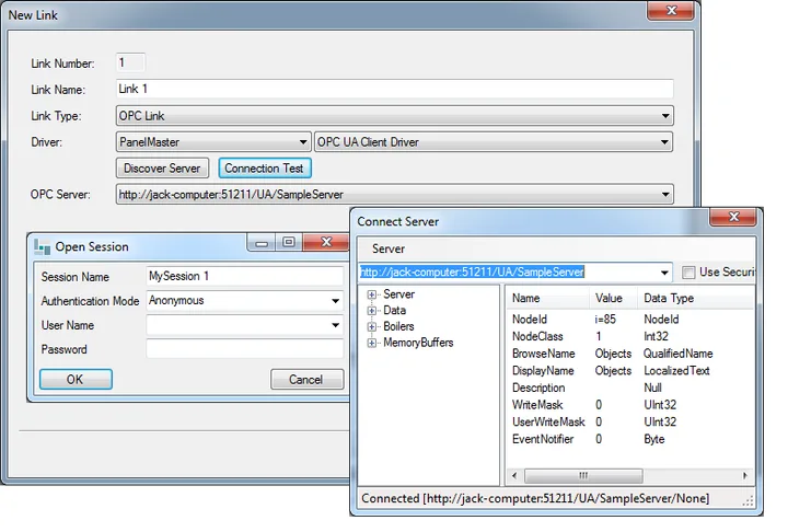
5) After a successful connection test to an OPC Server, the address of that OPC Server will be cached by The configuration program in order for future use.
■ NEO OPC UA Client Panels
Once
the connection to an
OPC
UA Server has been established, the OPC UA Client populates the following panels as shown in the Figure below:
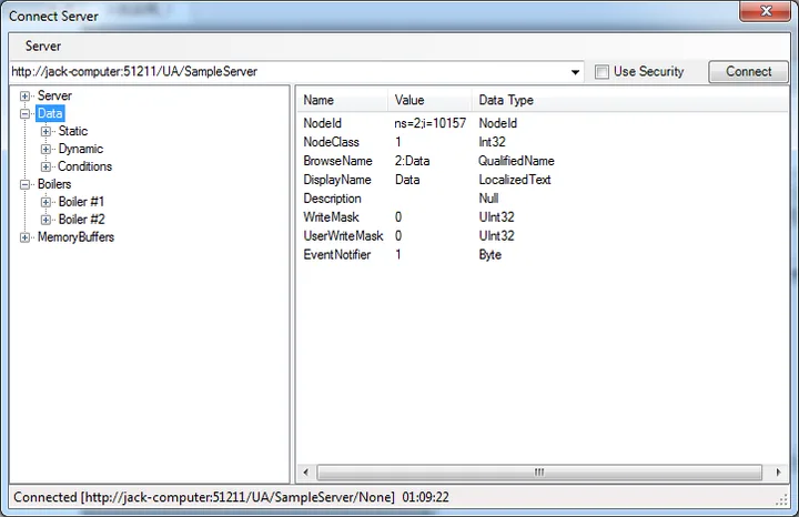
An example of Server’s Address Space of http://jack-computer:51211/UA/SampleServer
The browse panel available on the left displays the object instances in the Server’s Address Space while the property panel on the right shows the details of a given object instance.
The OPC UA Server’s Address Space is a full mesh network which can be viewed by expanding any of the nodes shown in the browse panel. While details of an object instance in the Server’s Address Space can be viewed by clicking its corresponding node. See OPC documentation for more detailed description about UA Server’s Address Space.
Under the Server menu, there is a Disconnect menu option. The current session can be closed at any time by clicking it.
■ Load Tags from OPC Server into The configuration program
All or part of an OPC Server’s Address Space can be loaded into The configuration program as tags for use as long as the data type (e.g. integer, floating) and value rank (e.g. one dimension or two dimensions) of an object instance are supported by The configuration program. Currently,
The supported data types are as the following:
- Boolean
- Byte
- SByte
- Float
- Int16
- Int32
- ByteString
- String
- UInt16
- UInt32
The supported value rank are as the following:
- Scalar
- One Dimension
- Two Dimensions
The object instances in the OPC Server’s Address Space with unsupported data type or value rank are automatically eliminated during loading tags from OPC Server into The configuration program.
Loading tags from OPC Server’s Address Space into The configuration program can
be accomplished in Tag Table dialog. By clicking the Load Tags from
OPC Server from the pop-up menu under the Link name as shown below. (Note:
the driver of the Link must be an OPC UA Client driver.)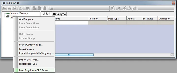
The OPC UA Client populates the following panels in which Server’s Address Space can be selected. Here, we select loading all the tags under Data node as an example.
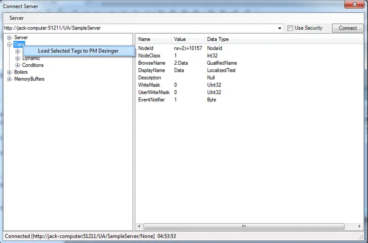
After clicking the Load Selected
Tags from OPC server, all the supported data tags under the Data node
are loaded to The configuration program as the Figure shown below.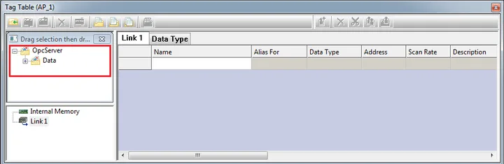
After that, drag the imported tag group
(or its sub-group), e.g. the OpcServer folder under the Link1 node.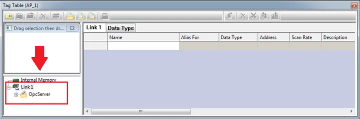
By clicking the corresponding node under the Link1 node (here take Scalar node
as an example), the detailed information of the tags are displayed on the right
side list.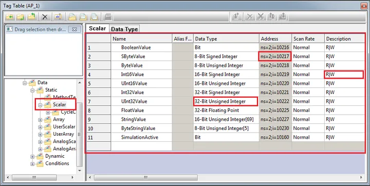
In the Figure above, the Data Type, Address, and Description of a given tag is listed one row in the table. Here, Address does not represent the physical address but an abstract address where an object instance stays in the OPC Server’s Address Space, while R/W in the Description field means that the property of an object instance is both Read and Write allowed. If it is read only, only R appears in that field.
Then, all the tags can be used as you have been already familiar with in The configuration program.
Need PM Designer itself?
V4 for current PK, PT, ITV and PM panels, V2 for older models. Free, sent by email.
Source.Section 3.4.12 of the PM Designer Software User Manual, Edition 2.0, © Cermate Technologies Inc. (www.cermate.com, service@cermate.com). Reproduced online, with the manual's own figures, by TSL Automation Solutions, authorised Cermate distributor, for users of Cermate HMI panels. PM Designer and PanelMaster are trademarks of Cermate Technologies Inc.
Text and figures are the manufacturer's and may describe features your panel or software version does not have. For a plain-language introduction read the PM Designer guide; for help with a specific panel contact TSL Automation.