
Section 3.4.7 · Chapter 3: Creating Panel Applications
Writing Communication Programs Using Macro Commands
You can write a macro program to let your HMI communicate with a computing device through a serial port. For simplicity, we will use Device in the following sections to refer to the target computing device.
- Create a communication link for the application to connect the panel and Device.
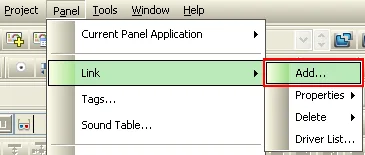 or
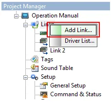
-
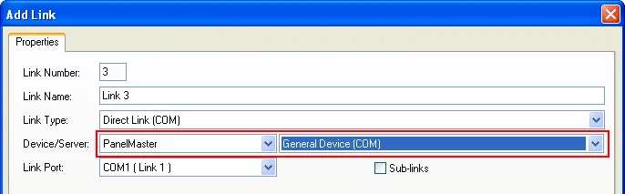
Specify the general settings for the link. You need to select PanelMaster - General Device (COM) as the device to be connected.
-
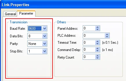
Specify the parameters of the communication.
-
Understand the key words that are available for composing the communication macro programs.
|
Key Word |
Type | R/W | Function | ||
|---|---|---|---|---|---|
| TX | Word | Write Only |
Writing a block of words to TX transmits the low bytes
of that block of words to Device. The write operation is
done when the transmission starts or is cancelled. Example: $U10 = "ABC" $U20 = B2W($U10, 3) // Convert the byte array to a word array TX = MOV($U20, 3) // Transmit “ABC” to Device Operation rules: 1) The transmission cannot start until the previous transmission has finished. 2) The word TXT_STS will be set to 1 when the transmission starts. 3) When the hardware flow control is enabled (Bit EN_HS is set to 1), the transmission will not start until the device allows the panel to send data (The CTS signal on the port is asserted). 4) When the RTS/CTS flow control is enabled (Bit EN_HS is set to 1), the RTS signal on the serial port will be negated when the transmission starts and it will be asserted when the transmission ends. 5) The transmission will be cancelled if it cannot start after waiting a time specified by the word TO_TIME. The word TX_STS will be set to 2 when the timeout condition occurs. |
||
| TX_W | Word | Write Only | TX_W provides the same functionality as TX, except that the write operation is done after all the bytes are transmitted. It is recommended to use TX_W to transmit data as the macro program will not waste time to wait for the completion and the CPU of the panel will be utilized more efficiently. | ||
| TX_STS | Word | Read Only | Reading this word gets the status of the last transmission. | ||
| Value | Status | ||||
| 1 | Succeeded | ||||
| 2 | Timeout | ||||
| 255 | In progress | ||||
| RX | Word | Read Only |
Reading this word copies a specified number of word
values from the receive buffer. The receive buffer is a
word array. The bytes received from Device are stored in
the low bytes of the buffer. The high bytes of the
buffer are always 0. Once the received data are copied,
they are removed from the receive buffer. The read
operation is executed whether or not there are enough
bytes received in the buffer. Example: $U10 = MOV(RX, 3) // Receive 3 words from the receive buffer. // $U10 gets the value of the first received byte. // $U11 gets the value of the second received byte. // $U12 gets the value of the third received byte. Operation rules: Assume the number of words to be read from the buffer is n and the number of available words in the buffer is m. 1) If there are enough data received in the buffer, the read operation does the following 4 things: copies the first n words in the buffer to the destination, sets RX_CNT to n, sets RXB_CNT to (m-n), and sets RX_STS to 1. 2) If there are not enough data received in the buffer, the read operation does the following 4 things: copies all the available data to the destination, sets RX_CNT to m, sets RXB_CNT to 0, and sets RX_STS to 1. 3) When the request size of using RX to get the received characters is larger than RX_CNT, the words that get no received characters will be reset to 0. |
||
| RXB_CNT | Word | Read Only | Reading this word gets the number of words that are available in the receive buffer. Note that one word of the receive buffer contains one received byte. | ||
| RX_CNT | Word | Read Only | Reading this word gets the number of words that were actually taken out of the receive buffer by the last receive operation. Note that one word of the receive buffer contains one received byte. | ||
| RX_STS | Word | Read Only | Reading this word gets the status of the last receive operation. | ||
| Word Value | Description | ||||
| 1 | Succeeded | ||||
| 2 | Timeout | ||||
| Others | Failed | ||||
| RX_W | Word | Read Only |
Reading this word copies a specified number of word
values from the receive buffer. The receive buffer is a
word array. The bytes received from Device are stored in
the low bytes of the buffer. The high bytes of the
buffer are always 0. Once the received data are copied,
they are removed from the receive buffer. If there are
not enough data received in the buffer, the read
operation will wait a time specified by TO_TIME. The
read operation will not complete until all the required
data are received or the timeout occurs. Example: $U10 = MOV(RX_W, 3) // Receive 3 words from the receive buffer. // Wait for the data if they are not received from Device yet. // $U10 gets the value of the first received byte. // $U11 gets the value of the second received byte. // $U12 gets the value of the third received byte. Operation rules: Assume the number of words to be read from the buffer is n and the number of available words in the buffer is m 1) If there are enough data received in the buffer, the read operation does the following 4 things: copies the first n words in the buffer to the destination, sets RX_CNT to n, sets RXB_CNT to (m-n), and sets RX_STS to 1. 2) If there are not enough data received in the buffer, the read operation will wait a time specified by TO_TIME for the required data to come. When enough data are received, the read operation performs rule 1 above. When timeout occurs, the read operation is cancelled and RX_STS is set to 2. |
||
| FLUSH | Bit | Write Only | Writing 1 to this bit flushes the receive buffer that is used to receive data from Device. | ||
| RESET | Bit | Write Only | Writing 1 to this bit resets the UART that is used for the communication between the panel and Device. | ||
| TO_TIME | Word | Read/Write |
Writing the timeout time to this word sets the timeout
time for the communication. The unit is 0.1 second. Example: TO_TIME = 20 (U) // Set the timeout time to 2 second. |
||
| EN_HS | Bit | Read/Write | Writing 1 to the bit enables the RTS/CTS flow control. | ||
| Bit Value | Function | ||||
| 0 | Disables the hardware flow control. | ||||
| 1 | Enables the hardware flow control. | ||||
|
Example: EN_HS = 1 (B) // Enable the flow control |
|||||
| CTS_STS | Bit | Read Only | Reading the bit gets the status of the CTS signal from the device. | ||
| Bit Value | CTS Signal | Comment | |||
| 0 | Asserted | The panel is allowed to send data to Device. | |||
| 1 | Negated | The panel is not allowed to send data to Device. | |||
|
Example: IF !CTS_STS (B) // Do the following when the CTS is asserted TX = MOV($U100, 10) // Send 10 bytes to Device ENDIF |
|||||
| RTS | Bit | Read/Write | Writing 0 to the bit asserts the RTS signal on the port. | ||
| Bit Value | Function | ||||
| 0 | Asserts the RTS signal. The Device is allowed to send data to the panel. | ||||
| 1 | Negates the RTS signal. The Device is not allowed to send data to the panel. | ||||
|
Example: RTS = 1 (B) // Disallow Device to send data to the panel |
|||||
- Understand the communication protocol.
- Write the program. The following is an example:
| $U10 = "ABCDE" | // $U10 = 4241H, $U11 = 4443H, $U12 = 4500H | |
| $U20 = B2W($U10,5) | // $U20 = 0041H, $U21 = 0042H, $U22 = 0043H, $U23 = 0044H, $U24 = 0045H | |
| TX_W = MOV($U20,5) | // Send 5 words("ABCDE") in $U20 to TX and wait until all datum are sent | |
| $U25 = 0DH | // 0DH is ASCII code for return character | |
| TX_W = MOV($U20,6) | // Send 6 words("ABCDE<CR>") in $U20 to TX and wait until all datum are sent | |
| TX_W = MOV($U20,5) | // Send 5 words in $U20 to TX | |
| $U100 = MOV(RX,5) | // Read 5 words from RX to $U100 | |
| $U100 = MOV(RX_W,5) | // Read 5 words from RX to $U100 and wait until all datum are received | |
| RESET = 1 (B) | // Reset TX UART and clear RX buffer | |
| FLUSH = 1 (B) | // Clear RX buffer |
Need PM Designer itself?
V4 for current PK, PT, ITV and PM panels, V2 for older models. Free, sent by email.
Source.Section 3.4.7 of the PM Designer Software User Manual, Edition 2.0, © Cermate Technologies Inc. (www.cermate.com, service@cermate.com). Reproduced online, with the manual's own figures, by TSL Automation Solutions, authorised Cermate distributor, for users of Cermate HMI panels. PM Designer and PanelMaster are trademarks of Cermate Technologies Inc.
Text and figures are the manufacturer's and may describe features your panel or software version does not have. For a plain-language introduction read the PM Designer guide; for help with a specific panel contact TSL Automation.