
Section 3.4.8.1 · Chapter 3: Creating Panel Applications
Setting up Gateway Service
We describe how to set up a gateway service with an example here. Suppose that the panel application has two links: The link 1 connects a PanelMaster Null PLC to the panel through COM1 and the link 2 connects a Siemens AG Simatic S7-300(MPI Port) through COM2. A program running on a PC will access the memory locations listed in the following table through the panel and Ethernet using the Modbus TCP/IP protocol.
| Memory Locations To Be Accessed | Memory Type | Size | Link No. | Modbus Addresses Used By The PC Program |
|---|---|---|---|---|
| $N100.0 ~ N100.f | Bit | 1 (16 bits) | Internal Memory | 10001 ~ 10016 |
| W20.0 ~ W21.f | Bit | 2 (32 bits) | 1 | 10100 ~ 10131 |
| Q10.0 ~ Q13.7 | Bit | 2 (32 bits) | 2 | 10350 ~ 10381 |
| $U300 ~ $U319 | Word | 20 words | Internal Memory | 40001 ~ 40020 |
| W250 ~ W289 | Word | 40 words | 1 | 40100 ~ 40139 |
| MW70 ~ MW129 | Word | 30 words | 2 | 40200 ~ 40229 |
The following shows the steps to set up the gateway service:
- Add a new link. In this example, the number of the new link is 3.
- In the Link Properties dialog box, select "Gateway Service (Ethernet)" as the Link Type and select "PanelMaster TCP/IP Gateway Server" as the Device/Server. Click the OK button to close the dialog box.
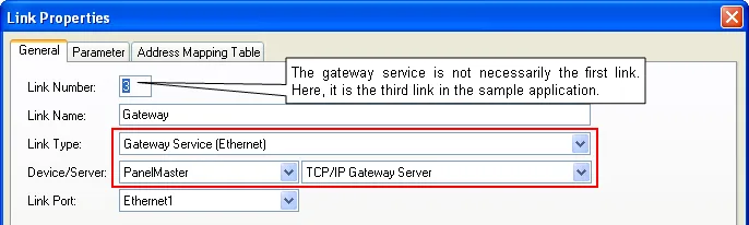
3. Open the dialog box again. Click the Address Mapping Table tab to specify the memory locations to be accessed by the PC program. Click the OK button after finishing the address mapping table. The following picture shows the address mapping table for the example.
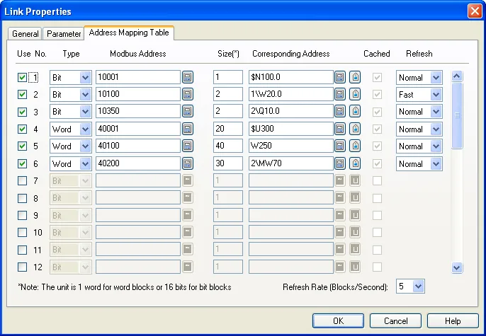
The following table describes each property in the Address Mapping Table page of the Link Properties dialog box for a Gateway Service (Ethernet) link.
|
Property |
Description |
|---|---|
| Use | Check the box to enable the associated mapping block. A mapping block maps a block of internal or external memory locations into the Modbus address space. A gateway client uses the addresses in the specified Modbus address range to access the mapped memory locations indirectly. |
| No | Shows the mapping block's number. |
| Type | Specifies the memory type of the mapping block. Select Bit for a bit block and Word for a word block. |
| Modbus Address | Specifies the Modbus address of the mapping block. |
| Size | Specifies the mapping block size. If the location type is Word, the unit is 1 word. If the location type is Bit, the unit is 16 bits. For example, when the size of a bit block is 3, the block size is 48 bits. The maximal size of a block is limited by the maximal read block size of the mapped memory block that can be transmitted in one communication transaction or 125 words if the maximal block read size is larger than 125 words. |
| Corresponding Address | Specifies the address of the internal or external memory block that the gateway client will use the Modbus address to access. |
| Refresh | Select the rate that the server will read the mapped memory block periodically to refresh the corresponding cache. In a period of time, a mapped memory block with Fast refresh rate will be read two times more than a mapped memory block with Normal refresh rate. |
Limitations:
- At most, 32 mapping blocks can be defined.
- When reading a block of words or bits, the words or bits must be within a single mapping block, or the read operation will fail.
Need PM Designer itself?
V4 for current PK, PT, ITV and PM panels, V2 for older models. Free, sent by email.
Source.Section 3.4.8.1 of the PM Designer Software User Manual, Edition 2.0, © Cermate Technologies Inc. (www.cermate.com, service@cermate.com). Reproduced online, with the manual's own figures, by TSL Automation Solutions, authorised Cermate distributor, for users of Cermate HMI panels. PM Designer and PanelMaster are trademarks of Cermate Technologies Inc.
Text and figures are the manufacturer's and may describe features your panel or software version does not have. For a plain-language introduction read the PM Designer guide; for help with a specific panel contact TSL Automation.