
Section 3.4.2 · Chapter 3: Creating Panel Applications
General Settings for Commnunication Links
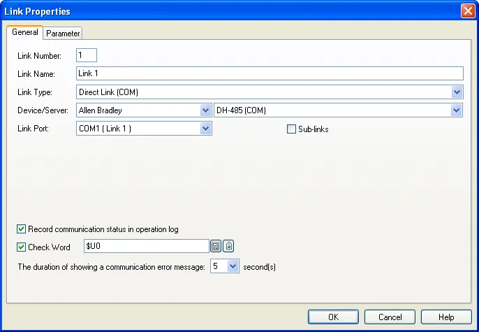
This section describes how to define the general settings for the communication links using the General page of the Link Properties dialog box. The following is an example of the General page that defines a direct link.
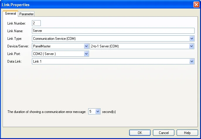
The following is an example of the General page that defines a communication service link.
The following table describes each property in the General page of the Link Properties dialog box.
|
Property |
Description | ||
|---|---|---|---|
| Link Number | The sequence number of the communication link. It is assigned when the link is created and reassigned when any other link of the same application is removed. | ||
| Link Name | Specifies the name of the communication link. | ||
| Link Type | Select one of the following link types for the link: | ||
| Link Type | Description | ||
| Direct Link (COM) | The link connects to the specified device directly through the specified serial (COM) port. | ||
| Direct Link (Ethernet) | The link connects to the specified device directly through the specified Ethernet port. | ||
| Communication Service (COM) | The link connects to one or more other target panels through the specified serial (COM) port and provides the communication service specified in the Device/Server field to the connected target panels. See the description of the Device/Server field to know the available communication services. | ||
| Communication Service (Ethernet) | The link connects to one or more other target panels through the specified Ethernet port and provides the communication service specified in the Device/Server field to the connected target panels. See the description of the Device/Server field to know the available communication services. | ||
| Gateway Service (COM) | The panel performs as a communication gateway to allow a computing device, which is connected to the panel through a serial link and the specified COM port, to access the panel's internal memory and the controllers connected to the panel. | ||
| Gateway Service (Ethernet) | The panel performs as a communication gateway to allow one or more computing devices, which are connected to the panel through a Ethernet link, to access the panel's internal memory and the controllers connected to the panel. | ||
| Indirect Link via 2-to-1 Connection (COM) | The link connects to a target panel that provides the communication service as a 2-to1 server through the specified serial (COM) port. The target panel can communicate with the associated device indirectly through that target panel. | ||
| Indirect Link via N-to-1 Connection (COM) | The link connects to a target panel that provides the communication service as an N-to1 master through the specified serial (COM) port. The target panel can communicate with the associated device indirectly through that target panel. | ||
| Indirect Link via N-to-1 Connection (Ethernet) | The link connects to a target panel that provides the communication service as an N-to1 master through the specified Ethernet port. The target panel can communicate with the associated device indirectly through that target panel. | ||
| OPC Link | |||
| Device/Server |
When the Link Type is Direct Link, specify
the link’s connected device.
When the Link Type is Communication Service (COM), select one of the following servers. |
||
| Server | Description | ||
| 2-to-1 Server | In the Data Link field, specify a direct link of the application as the data link for the server. The 2-to-1 server is a bridge between another panel and the device connected to the specified data link. Another panel/application of the project can now use an indirect link to access the device connected to the server through the specified data link. | ||
| 2-to-1 Transparent Server | In the Data Link field, specify a direct link of the application as the data link for the server. The service link connects to a computing device, and allows the device to indirectly communicate with another device through the data link. The computing device can be a target panel, a panel of another brand, or a PC. If the computing device is a target panel, it must use a direct link to accept the service. | ||
| N-to-1 Master | In the Data Link field, specify a direct link of the application as the data link for the server. The link can connect up to 8 target panels, and allow these panels to indirectly communicate with the device connected to the specified data link. The panels served by the link must use an indirect link to accept the service. | ||
| When the Link Type is Communication Service (Ethernet), select one of the following servers. | |||
| Server | Description | ||
| N-to-1 Master | In the Data Link field, specify a direct link of the application as the data link for the server. The link can connect up to 8 target panels, and allow these panels to indirectly communicate with the device connected to the specified data link. The panels served by the link must use an indirect link to accept the service. | ||
| When the Link Type is Indirect Link and the Indirect Link Server Location is specified, the indirectly connected device is shown here. | |||
| Link Port | Select a port for this link. | ||
| Sub-links |
When an RS485 communication line has many devices
connected to it, the logical connection of a device on
the link with the target panel is called a sub-link. This field is available when the Link Type is Direct Link (COM). Select this option if this link will connect to many devices, and you want to identify, monitor, or control the communication with each connected device. |
||
| Data Link | Select a direct link of the application as the data link for the communication service when the Link Type is Communication Service. | ||
| Indirect Link Server Location | Panel Application | Select the panel application that provides the communication service for this indirect link. | |
| Link | Select the communication service link that provides the communication service for this indirect link. | ||
| Record communication status in operation log | Check this option if you want the communication status of the link or the link’s sub-links to be recorded in the operation log. The recordable types of status include: Enabled, Disabled, Failed, and Recovered. The operation log display can show the logged communication status. | ||
| Check Word | The panel will read the specified word periodically to check the status of the link’s connection. | ||
| The duration of showing a communication error message | The communication error message box will hide and show according to the specified duration. If the duration is 0, the error message box will not show. | ||
Need PM Designer itself?
V4 for current PK, PT, ITV and PM panels, V2 for older models. Free, sent by email.
Source.Section 3.4.2 of the PM Designer Software User Manual, Edition 2.0, © Cermate Technologies Inc. (www.cermate.com, service@cermate.com). Reproduced online, with the manual's own figures, by TSL Automation Solutions, authorised Cermate distributor, for users of Cermate HMI panels. PM Designer and PanelMaster are trademarks of Cermate Technologies Inc.
Text and figures are the manufacturer's and may describe features your panel or software version does not have. For a plain-language introduction read the PM Designer guide; for help with a specific panel contact TSL Automation.