
Section 3.4.3 · Chapter 3: Creating Panel Applications
Communication Parameter Settings (Serial Port)
This section describes how to set up the communication parameters for the serial communication links using the Parameter page of the Link Properties dialog box.
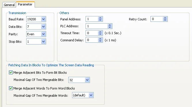
The following is an example of the Parameter page for a serial direct link.
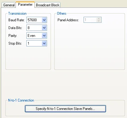
The following is an example of the Parameter page for an N-to-1 master.
The following table describes each property in the Parameter page of the Link Properties dialog box for a serial link.
|
Property |
Description |
|---|---|
| Baud Rate | The baud rate used. |
| Data Bits | The number of data bits used. |
| Parity | The scheme of parity used. |
| Stop Bits | The number of stop bits used. |
| Panel Address | The address of the target panel. |
| PLC Address | The address of the connected device. |
| Timeout Time | The maximum time allowed for the communication driver to wait for a reply from the connected device. When the elapsed time exceeds the Timeout Time, the communication driver assumes the communication failed. |
| Command Delay | If the Command Delay is 0, the communication driver immediately sends the next request to the connected device when it receives a reply from the last request. If the Command Delay is nonzero, the communication driver delays for the specified amount of time before sending the next request to the connected device. |
| Retry Count | The number of times the communication driver will retry for each request to get a successful reply from the connected device. If the number is zero, the communication driver will use the default retry count. |
| Fetching Data In Blocks To Optimize The Screen Data Reading |
The optimization of screen data reading for the serial
links can be determined by the developers. Check the
options and the developer can: a) Disable the optimization if the connected PLC does not support block read, and b) Adjust the criteria of forming read blocks so the optimization can be suited to each application. |
| Specify N-to-1 Connection Slave Panels | This button is available when the link is an N-to-1 master. Click this button to bring up the N-to-1 Connection Slave Panels dialog box. You can define the slave panels of the N-to-1 connection in the dialog box. |
| Specify Other Data Sharing Panels | This button is available when the link is a direct link and the connected device is Data Sharer (RS485). Click this button to bring up the Other Data Sharing Panels dialog box. You can define the other data sharing panels in the dialog box. |
Need PM Designer itself?
V4 for current PK, PT, ITV and PM panels, V2 for older models. Free, sent by email.
Source.Section 3.4.3 of the PM Designer Software User Manual, Edition 2.0, © Cermate Technologies Inc. (www.cermate.com, service@cermate.com). Reproduced online, with the manual's own figures, by TSL Automation Solutions, authorised Cermate distributor, for users of Cermate HMI panels. PM Designer and PanelMaster are trademarks of Cermate Technologies Inc.
Text and figures are the manufacturer's and may describe features your panel or software version does not have. For a plain-language introduction read the PM Designer guide; for help with a specific panel contact TSL Automation.