
Section 3.4.1 · Chapter 3: Creating Panel Applications
Types of Communication Links
The following table describes the three types of communication links that the panel application can have.
|
Link Type |
Description | |
|---|---|---|
| Direct link |
Directly connects the panel with the specified
device(s). The following are examples of direct links. [Example 1] The panel uses an RS232 direct link to talk with the specified device directly.  [Example 2] The panel uses an RS485 direct link to talk with the specified devices directly. 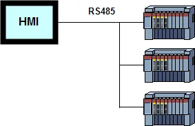 [Example 3] The panel uses an Ethernet direct link to talk with the specified device directly. 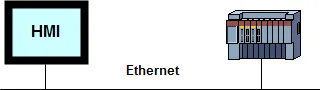 |
|
| Indirect link |
Allow the panel to talk with a device that is not
directly connected to it. An indirect link connects the
panel with a specified indirect link server. The
indirect link server is the target panel of a panel
application in the same project and is directly
connected to the specified device. [Example 1] Indirect Link via 2-to-1 Connection 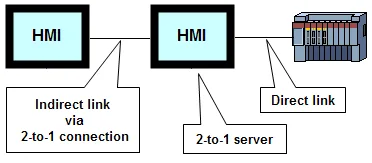 [Example 2] Indirect Link via N-to-1 Connection (COM) 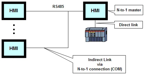 [Example 3] Indirect Link via N-to-1 Connection (Ethernet) 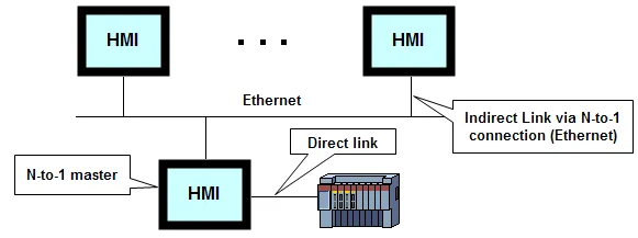 |
|
| Communication service | Add an appropriate communication service link to the application to allow other panels to communicate with the device directly connected to the target panel. The following table describes the available communication services. | |
| Communication Service | Description | |
| 2-to-1 Server (COM) | You need to specify the data link, i.e. the associated direct link, for this communication service. This service allows two panels to talk with one device, and only one communication port is required on that device. | |
| 2-to-1 Transparent Server (COM) |
This communication service makes the target panel a
gateway for another computing device, such as, a PC,
another target panel, or a panel of another brand, to
access the associated controller. See the following
diagrams for the possible applications.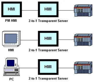 Any kind of controller whose communication protocol is of the request-reply type can be supported by this communication service. Ask your local representative to check if your controller is supported. Note that the communication parameters (baud rate, number of data bits, number of stop bits, and type of parity check) of the computing device and the communication parameters of the 2-to-1 Transparent Server must be identical. |
|
| N-to-1 Master (COM) | You need to specify the data link, i.e. the associated direct link, for this communication service. This service allows up to 16 HMI units to talk with one device, and only one communication port is required on that device. | |
| N-to-1 Master (Ethernet) | You need to specify the data link, i.e. the associated direct link, for this communication service. This service allows up to 24 HMI units to talk with one device, and only one communication port is required on that device. | |
| Gateway service | A panel can perform as a communication gateway to allow a computing device, such as a PC, to access the panel's internal memory and the controllers connected to the panel. The following table describes the available gateway servers. | |
| Gateway Service | Description | |
| Serial Gateway Server (COM) |
With the serial gateway server driver, a panel can perform as a communication gateway to allow a computing device, which is connected to the panel through a serial port, to access the panel's internal memory and the controllers connected to the panel. In the following figure, the panel has three direct links connected to three PLCs. The fourth link connects a PC to the panel. The three lines with different colors indicate the PC can indirectly access the three PLCs through the panel. The communication protocol used between the PC and the panel is Modbus RTU. Please see
Section 3.4.8 for details.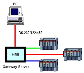 |
|
| TCP/IP Gateway Server (Ethernet) |
With the TCP/IP gateway server driver, a panel can perform as a communication gateway to allow one or more computing devices, which are connected to the panel through Ethernet, to access the panel's internal memory and the controllers connected to the panel. In the following figure, the panel has three direct links connected to three PLCs. The fourth link connects three computing devices to the panel
through Ethernet. The three lines with different colors indicates the three computing devices can indirectly access the three PLCs through the panel.
The communication protocol used between the computing devices and the server is Modbus TCP/IP. Please see
Section 3.4.8 for details.
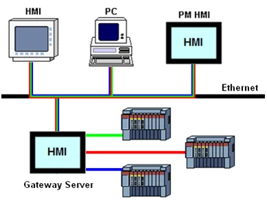 |
|
| Internal Memory Server (Ethernet) | With the internal memory server driver, a panel can perform as a communication gateway to allow one or more computing devices, which are connected to the panel through Ethernet, to access the panel's internal memory. The communication protocol used between the computing devices and the server is Modbus TCP/IP. Please see Section 3.4.10 for details. | |
| OPC Link | OPC Link | Description |
| OPC UA Client Driver | The OPC Client Driver allows the aggregation of data from Third-Party OPC UA servers and any other data that HMI unit may be monitoring. It provides a communications tunnel between two or more computing devices such as PC, HMI units, allowing data to be transferred securely and reliably. | |
Need PM Designer itself?
V4 for current PK, PT, ITV and PM panels, V2 for older models. Free, sent by email.
Source.Section 3.4.1 of the PM Designer Software User Manual, Edition 2.0, © Cermate Technologies Inc. (www.cermate.com, service@cermate.com). Reproduced online, with the manual's own figures, by TSL Automation Solutions, authorised Cermate distributor, for users of Cermate HMI panels. PM Designer and PanelMaster are trademarks of Cermate Technologies Inc.
Text and figures are the manufacturer's and may describe features your panel or software version does not have. For a plain-language introduction read the PM Designer guide; for help with a specific panel contact TSL Automation.