
Section 3.4.10 · Chapter 3: Creating Panel Applications
Accessing Internal Memory through Ethernet
This section describes how to configure HMI units so that they can access the internal memories of others through Ethernet.
■ Making the Internal Memory Accessible
To make the internal memory of an HMI unit accessible to other HMI units, you need to create the following communication link for the accessed HMI unit.
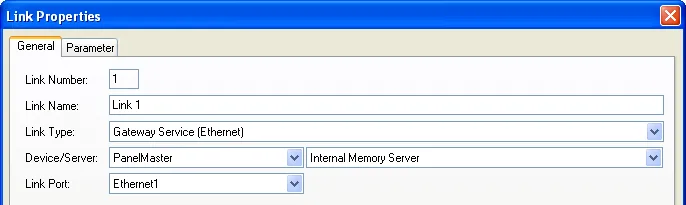
Note:
1) The Modbus TCP/IP
protocol is used.
2) The internal memory
server can support up to 8 clients.
3) The maximal number of words that can be read once is 125.
4) The maximal number of words that can be written once is
120.
5) The maximal number of bits that can be read once is 2000.
6) The maximal number of bits that can be written once is
800.
7) If the specified internal memory address or range is
invalid or unavailable, the request is failed.
8) The driver name is C2C301.
■ Enabling the Access of Internal Memory
To enable an HMI unit to access the internal memory of another HMI unit through Ethernet, you need to create the following communication link for the accessing HMI unit.
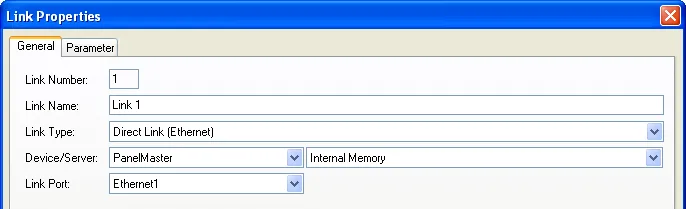
Remember to specify the IP address of the accessed HMI unit in the Parameter page.
Note:
1) There is no limitation on the number of data per read and
write operations.
2) The driver name is C2C311.
The following table describes the addresses that you can use to refer to the internal memory of the accessed HMI unit.
| Address Range | Corresponding Internal Memory Addresses Range | R/W | Remark |
|---|---|---|---|
| N0.0-S4094.f | $N0.0-$N4094.f | R | The first 65535 bits of the battery backed user memory |
| U0.0-N4094.f | $U0.0-$U4094.f | R/W | The first 65535 bits of the regular user memory |
| U0-U8388607 | $U0-$U8388607 | R/W | The regular user memory |
| N0-N8388607 | $N0-$N8388607 | R/W | The battery backed user memory |
| R0:0-R0:8388607 | $R0:0-$R0: 8388607 | R/W | The recipe block No. 0 |
| R1:0-R1: 8388607 | $R1:0-$R1: 8388607 | R/W | The recipe block No. 1 |
| R2:0-R2: 8388607 | $R2:0-$R2: 8388607 | R/W | The recipe block No. 2 |
| … | … | … | … |
| R15:0-R15: 8388607 | $R15:0-$R15: 8388607 | R/W | The recipe block No. 15 |
■ Modbus Masters/Clients Can Also Be Clients
A Modbus master/client that supports 5-digit addresses can access part of
the internal memory thanks to the internal memory server.
The following table describes the addresses that a Modbus master/client can use to access the internal memory of an HMI unit.
| Modbus Addresses | Internal Memory Addresses | R/W | Remark |
|---|---|---|---|
| 1-65535 | $U0.0-$U4095.e | R/W | The first 65535 bits of the regular user memory |
| 100001-165535 | $N0.0-$N4095.e | R | The first 65535 bits of the battery backed user memory |
| 300001-365535 | $N0-$N65534 | R | The first 65535 words of the battery backed user memory |
| 400001-465535 | $U0-$U65534 | R/W | The first 65535 words of the regular user memory |
A Modbus master/client that supports function codes 20 (Read General Reference) and 21 (Write General Reference) can access all of the accessible internal memory thanks to the internal memory server.
The following table describes the addresses that a Modbus master/client can use to access the internal memory of an HMI unit.
| Modbus Reference Type | Modbus Reference Number | Corresponding Internal Memory Addresses | Remark |
|---|---|---|---|
| 0 | 0-8388607 | $U0-$U8388607 | The regular user memory |
| 1 | 0-8388607 | $N0-$N8388607 | The battery backed user memory |
| 3 | 0-8388607 | $R0:0-$R0: 8388607 | The recipe block No. 0 |
| 4 | 0-8388607 | $R1:0-$R1: 8388607 | The recipe block No. 1 |
| 5 | 0-8388607 | $R2:0-$R2: 8388607 | The recipe block No. 2 |
| ... | ... | ... | ... |
| 18 | 0-8388607 | $R15:0-$R15: 8388607 | The recipe block No. 15 |
Note:
1) The internal memory server supports only one group
at a time for function codes 20 and 21.
Need PM Designer itself?
V4 for current PK, PT, ITV and PM panels, V2 for older models. Free, sent by email.
Source.Section 3.4.10 of the PM Designer Software User Manual, Edition 2.0, © Cermate Technologies Inc. (www.cermate.com, service@cermate.com). Reproduced online, with the manual's own figures, by TSL Automation Solutions, authorised Cermate distributor, for users of Cermate HMI panels. PM Designer and PanelMaster are trademarks of Cermate Technologies Inc.
Text and figures are the manufacturer's and may describe features your panel or software version does not have. For a plain-language introduction read the PM Designer guide; for help with a specific panel contact TSL Automation.