TSL Automation Solutions Logo
Chapter 3: Creating Panel Applications: 54 topics
  1. 3.1Setting up the Panel Application
  2. 3.1.1General Setup - General Settings
  3. 3.1.2General Setup - Custom Settings
  4. 3.1.3Activating Multiple Overlapped Buttons by One Touch
  5. 3.1.4Specifying Default Folder for File I/O
  6. 3.1.5Avoiding Data Corruption Due To Random Power-off
  7. 3.2Working with Keys
  8. 3.2.1Default Key Settings for the Panel Application
  9. 3.2.2Key Settings for a Screen
  10. 3.2.3Key Usage Table Settings
  11. 3.2.4Usage Settings for a Key
  12. 3.3Internal Memory
  13. 3.3.1Types of Internal Memory
  14. 3.3.2Index Registers
  15. 3.3.3System Memory
  16. 3.3.4Setting up Internal Memory
  17. 3.4Communication Links
  18. 3.4.1Types of Communication Links
  19. 3.4.2General Settings for Commnunication Links
  20. 3.4.3Communication Parameter Settings (Serial Port)
  21. 3.4.4Communication Parameter Settings (Ethernet Port)
  22. 3.4.5Sub-link Settings
  23. 3.4.6Sharing Data among Panels Using Data Sharer
  24. 3.4.7Writing Communication Programs Using Macro Commands
  25. 3.4.8Using Gateway Server of the Target Panel
  26. 3.4.8.1Setting up Gateway Service
  27. 3.4.9Selecting Modbus Communication Drivers
  28. 3.4.10Accessing Internal Memory through Ethernet
  29. 3.4.11Accessing Siemens PLC through Ethernet
  30. 3.4.12Using the OPC UA Client Driver
  31. 3.5Sound Table
  32. 3.6Command Block and Status Words
  33. Types of Command Block and Status Words
  34. 3.6.1.1Command & Status - Type A
  35. 3.6.1.2Command & Status - Type H (Binary)
  36. 3.6.1.3Command & Status - Type H (BCD)
  37. 3.6.2Command & Status - General Settings
  38. 3.6.3Command Block Settings (Type A)
  39. 3.6.4Status Word Settings (Type A)
  40. 3.6.5Command Block Settings (Type H)
  41. 3.6.6Status Word Settings (Type H)
  42. 3.6.7Using General Commands
  43. 3.7Setting up Clock Operations
  44. 3.8Setting up Passwords
  45. Screens
  46. 3.9.1Types of Screens
  47. 3.9.2Creating and Opening Screens
  48. 3.9.3Setting up a Screen
  49. 3.9.3.1Screen - General Page
  50. 3.9.3.2Screen - Background Page
  51. 3.9.4Importing/Exporting a Screen
  52. 3.9.5Cutting/Copying/Pasting/Deleting a Screen
  53. 3.9.6Saving Screens as Pictures
  54. 3.9.7Protecting Screens
All 20 chapters →

Section 3.4.6 · Chapter 3: Creating Panel Applications

Sharing Data among Panels Using Data Sharer

The data sharer is a virtual device. It allows data sharing among up to 16 target panels on an Ethernet or an RS485 network. Each of the target panels can have up to 256 words of data to share.
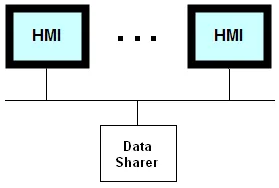
To set up the communication for data sharing, create a direct link and select Data Sharer (UDP) or Data Sharer (RS485) as the connected device. The panel address that you can set in the Parameter page of the Link Properties dialog box must be unique for each sharing panel as it is used to identify the shared data.

The communication driver for the link connecting to Data Sharer is responsible for broadcasting the panel's shared data on the network. For example, if the panel address of a panel is 10 and the number of the link connecting to Data Sharer is 2, the following Macro command will cause the communication driver to broadcast the corresponding data on the network.

2\P10.0 = MOV($u300, 30)

The communication driver receives the broadcasted shared data on the network automatically. It has a block of memory to store the shared data. To access a word, use the following address, where m is the panel address and n is the word number of that panel’s shared data.

Pm.n m=1~16; n=0-255

To access a bit, use the following address, where b is a hexadecimal number representing the bit number in the specified word.

Pm.n.b m=1~16; n=0-255; b=0~f

The UDP is used for the data sharing on Ethernet.

Need PM Designer itself?

V4 for current PK, PT, ITV and PM panels, V2 for older models. Free, sent by email.

Source.Section 3.4.6 of the PM Designer Software User Manual, Edition 2.0, © Cermate Technologies Inc. (www.cermate.com, service@cermate.com). Reproduced online, with the manual's own figures, by TSL Automation Solutions, authorised Cermate distributor, for users of Cermate HMI panels. PM Designer and PanelMaster are trademarks of Cermate Technologies Inc.

Text and figures are the manufacturer's and may describe features your panel or software version does not have. For a plain-language introduction read the PM Designer guide; for help with a specific panel contact TSL Automation.